


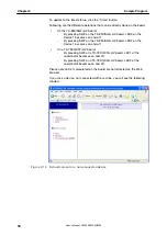


Figure 2-7 WriteEZ3 Device Setup
Write the same sample programs to the other TK-78K0/KF2+UZ boards.
Then, set the position of the switches as shown below:
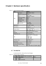
Table 2-3 Operation mode setting for the TK-78K0/KF2+UZ
SW1 – 1, 2, 3, 4, 5, 6 and 7
OFF
SW1 - 8
ON
SW5
UART
When you run the application, you can run it as a stand-alone system by setting
JP1 to 2-3 pin short and using a 6LR61 9V battery connected to CN2. For further
details about the power supply settings, please refer to section
.
Apply the relevant power supply source to the target boards.
If you select [Display] -> [Network Configuration] and if a Device is connected
wirelessly, you can see the red line.
Sample Program
Chapter 2
User's Manual U19026EE3V0UM00
15


