background image

22


SX-Aurora TSUBASA A300-

4 User’s Guide


Removing the Outer Rails from the Rack


In the uncommon event that it is necessary to remove the outer rails from the rack, follow 

these instructions. The chassis must be out of the rack.


Releasing the Outer Rails


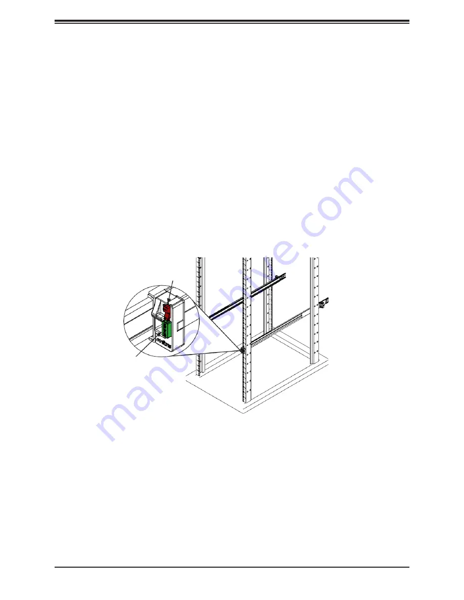
1.  On the front of the outer rail, slide the small plastic safety slider (red in drawing) up and 

hold it while pushing the plastic release button (green in drawing) just below it.


2.  While holding the release button in, pull the outer rail forward to disengage the pins and 

the front of the rail from the rack.


3.  Support the front of the outer and middle rail assembly while releasing the rear.


4.  Remove the outer rail from the rear of the rack in the same way as the front. Slide the 

safety slider up and push and hold the release button, then pull the rear pins out of the 
rack and remove the  rail.


Figure 2-7. Removing the Outer Rails


Safety Slider


Release Button


Summary of Contents for SX-Aurora TSUBASA A300-4

Page 1: ...SX Aurora TSUBASA A300 4 USER S GUIDE Revision 1 0b ...

Page 2: ...LL NOT HAVE LIABILITY FOR ANY HARDWARE SOFTWARE OR DATA STORED OR USED WITH THE PRODUCT INCLUDING THE COSTS OF REPAIRING REPLACING INTEGRATING INSTALLING OR RECOVERING SUCH HARDWARE SOFTWARE OR DATA The products sold by NEC are not intended for and will not be used in life support systems medical equipment nuclear facilities or systems aircraft aircraft devices aircraft emergency communication dev...

Page 3: ...our system to work properly please follow the links below to download all necessary drivers utilities and the user s guide for your server NEC product manuals http www nec com en global prod hpc aurora document Product safety info http www nec com en global prod hpc aurora document safety_information pdf This Guide may be periodically updated without notice Please check the NEC website for possibl...

Page 4: ... Choosing a Setup Location 13 Rack Precautions 13 Server Precautions 14 Rack Mounting Considerations 14 2 3 Installing the Rails 16 Identifying the Rails 16 Releasing the Inner Rail 17 Installing The Inner Rails on the Chassis 18 Installing the Outer Rails on the Rack 19 Installing the System into the Rack 20 Removing the System From the Rack 21 Removing the Outer Rails From the Rack 22 Chapter 3 ...

Page 5: ... damaged in any way If any equipment appears damaged please file a damage claim with the carrier who delivered it Decide on a suitable location for the rack unit that will hold the server It should be situated in a clean dust free area that is well ventilated Avoid areas where heat electrical noise and electromagnetic fields are generated It will also require a grounded AC power outlet nearby Be s...

Page 6: ...S R2K05P2 CPU Supports dual Intel Xeon 6148 6126 4108 series Socket P0 LGA3647 processors Socket Type Socket P0 LGA3647 Memory 96GB or 192GB Chipset PCH C621 PCIe Cards Up to four Vector Engine 1 0 cards Up to two InfiniBand HCA cards Hard Drives one fixed 2 5 internal drive Power 2000W redundant power supply modules Form Factor 1U rackmount Dimensions WxHxD 17 2 x 1 7 x 35 2 in 437 x 43 x 894 mm ...

Page 7: ...ing 5 Power LED Indicates power is being supplied to the system power supply units This LED should normally be illuminated when the system is operating 6 UID LED The unit identification UID button turns on or off the blue light function of the Information LED and the blue LED on the rear of the chassis These are used to locate the server in large racks and server banks 7 Power Button The main powe...

Page 8: ...this function to locate the server in a rack mount environment Blinking blue Remote UID is on Use this function to identify the server from a remote location Front Features The chassis is a 1U rack mount chassis See the illustration below for the features included on the front of the chassis 1 1 2 Figure 1 2 Chassis Front View Front Chassis Features Item Feature Description 1 Hard Drive Bays Two 2...

Page 9: ...1 1 2 Figure 1 3 Chassis Rear View Rear Chassis Features Item Feature Description 1 Power Supply Module Redundant 2000W power supply 2 I O Ports See Section 1 6 for details 3 LP1 Slot PCI E 3 0 x16 card for InfiniBand HCA 4 LP2 Slot PCI E 3 0 x16 card for InfiniBand HCA 5 and 6 FHFL 2 Slot PCI E 3 0 x16 for Vector Engine Card ...

Page 10: ... 1 3 2 1 DMI3 PCH 6 0 Gb S USB 2 0 0 1 USB2 0 SPI Bus S W Temp Sensor W83773 at SMBUS TPM HEADER Debug Card FRONT PANEL SPI SPI SATA PCIex4 or Flexible I O BMC AST2500 1 0 3 2 RSC GN2 A68 CPU0 PCIe X16 CPU1 PCIe X8 NVME X8 SLOT 5 AOM PIO i2XT Rear IO riser card DMI3 SLOT 2 SLOT 4 SLOT 1 Two riseroptions RSC G A66 SLOT 3 FAN SPEED CTRL SYSTEM POWER BIOS BMC Boot Flash M 2 DDR4 ESPI PCIE x4 or SATA ...

Page 11: ...LED Indicator Section for LAN LED information SATA Ports The X11DGQ includes a total of four SATA3 ports I SATA0 3 Universal Serial Bus USB Ports There are two USB 3 0 ports USB2 3 on the I O back panel Back Panel USB2 3 USB3 0 Pin Definitions Pin Definition Pin Definition 1 VBUS 10 Power 2 D 11 USB 2 0 Differential Pair 3 D 12 4 GND 13 Ground of PWR Return 5 Stda_SSRX 14 SuperSpeed Receiver 6 Std...

Page 12: ...ndicators Unit ID LED A rear UID LED indicator at LE1 is located near the UID switch on the back panel This UID indicator provides easy identification of a system unit that may need service UID LED Indicator LED Color Definition Blue on Unit Identified ...

Page 13: ...ted in a clean dust free area that is well ventilated Avoid areas where heat electrical noise and electromagnetic fields are generated Leave enough clearance in front of the rack so that you can open the front door completely 25 inches and approximately 30 inches of clearance in the back of the rack to allow sufficient space for airflow and access when servicing This product should be installed on...

Page 14: ...rver from power surges and voltage spikes and to keep your system operating in case of a power failure Allow any drives and power supply modules to cool before touching them When not servicing always keep the front door of the rack and all covers panels on the servers closed to maintain proper cooling Rack Mounting Considerations Ambient Operating Temperature If installed in a closed or multi unit...

Page 15: ...tion should be given to power supply connections other than the direct connections to the branch circuit i e the use of power strips etc To prevent bodily injury when mounting or servicing this unit in a rack you must take special precautions to ensure that the system remains stable The following guidelines are provided to ensure your safety This unit should be mounted at the bottom of the rack if...

Page 16: ...ained and qualified personnel should be allowed to install replace or service this equipment Note This rail will fit a rack between 27 and 32 deep Identifying the Rails The chassis package includes two rail assemblies in the rack mounting kit Each assembly consists of three sections an inner rail that secures directly to the chassis an outer rail that secures to the rack and a middle rail that sli...

Page 17: ...dle Rail Front Latch Locking Lever on Inner Rail Inner Rail Figure 2 2 Extending the Rails and Releasing the Inner Rail Note Both front chassis rails and the rack rails have a locking tab which serves two functions First it locks the server into place when installed and pushed fully into the rack its normal operating position In addition these tabs lock the server in place when fully extended from...

Page 18: ...on the side of the chassis with the slotted holes in the inner rail 3 Slide the inner rail toward the rear of the chassis and under the T studs 4 An optional screw can be used to secure the rail to the chassis 2 3 Figure 2 3 Installing the Inner Rails Slide rail mounted equipment is not to be used as a shelf or a work space Warning do not pick up the server with the front handles They are designed...

Page 19: ...til the latch snaps into place 4 The outer rail is actually two pieces that slide to lengthen Pull out the rear of the outer rail adjusting the length until the square pin assembly passes then fits against the back of the rear post Be careful to keep the rail level 5 Insert the square pins at the rear of the outer rail into the square holes on the rear of the rack Push until the latch snaps into p...

Page 20: ...the middle rail 2 Align the inner rails on the chassis with the front of the middle rails and then push evenly on both sides of the chassis When partially in the locking levers will stop further progress 3 Press down the locking levers on the inner rails and push the chassis all the way into the rack The front latches will click into place Figure 2 5 Installing the System into the Rack Note Figure...

Page 21: ...completely press the release latches on each of the inner rails downward simultaneously and continue to pull the chassis out of the rack Caution It is dangerous for a single person to off load the heavy chassis from the rack without assistance Be sure to have sufficient assistance supporting the chassis when removing it from the rack or use a lift Figure 2 6 Removing the System from the Rack 1 1 ...

Page 22: ...t while pushing the plastic release button green in drawing just below it 2 While holding the release button in pull the outer rail forward to disengage the pins and the front of the rail from the rack 3 Support the front of the outer and middle rail assembly while releasing the rear 4 Remove the outer rail from the rear of the rack in the same way as the front Slide the safety slider up and push ...

Page 23: ...ance and BIOS Setting Chapter 3 Maintenance and BIOS Setting 3 1 Overview About maintenance and BIOS setting only trained and qualified personnel of NEC system should be allowed to install replace or service this equipment ...

Page 24: ... a fatal error occurs you should consult with your system manufacturer for possible repairs These fatal errors are usually communicated through a series of audible beeps The numbers on the fatal error list on the following page correspond to the number of beeps for the corresponding error All errors listed with the exception of Beep Code 8 are fatal errors BIOS Error Beep POST Codes Beep Code Erro...

Page 25: ...l means danger You are in a situation that could cause bodily injury Before you work on any equipment be aware of the hazards involved with electrical circuitry and be familiar with standard practices for preventing accidents 警告の定義 この警告サインは危険を意味します 人身事故につながる可能性がありますので いずれの機器でも動作さ せる前に 電気回路に含まれる危険性に注意して 標準的な事故防止策に精通 して下さい Warnung WICHTIGE SICHERHEITSHINWEISE Dieses Warnsymbol bedeutet Gefahr Sie be...

Page 26: ...Breaker Warning This product relies on the building s installation for short circuit overcurrent protection Ensure that the protective device is rated not greater than 250 V 20 A サーキット ブレーカー この製品は 短絡 過電流 保護装置がある建物での設置を前提としてい ます 保護装置の定格が250 V 20 Aを超えないこ とを確認下さ い Warnung Dieses Produkt ist darauf angewiesen dass im Gebäude ein Kurzschluss bzw Überstromschutz installiert ist Stellen Sie sicher dass d...

Page 27: ......

Page 28: ...d only through the use of a special tool lock and key or other means of security This warning does not apply to workstations アクセス制限区域 このユニットは アクセス制限区域に設置されることを想定しています アクセス制限区域は 特別なツール 鍵と錠前 その他のセキュリティの手段を用い てのみ出入りが可能です Warnung Diese Einheit ist zur Installation in Bereichen mit beschränktem Zutritt vorgesehen Der Zutritt zu derartigen Bereichen ist nur mit einem Spezialwerkzeug Schloss und Schlüsse...

Page 29: ...e Verbindungen entfernt werden Attention Cette unité peut avoir plus d une connexion d alimentation Pour supprimer toute tension et tout courant électrique de l unité toutes les connexions d alimentation doivent être débranchées Comply with Local and National Electrical Codes Warning Installation of the equipment must comply with local and national electrical codes 地方および国の電気規格に準拠 機器の取り付けはその地方および国の...

Page 30: ...al laws and regulations 製品の廃棄 この製品を廃棄処分する場合 国の関係する全ての法律 条例に従い処理する必要が あり ます Warnung Die Entsorgung dieses Produkts sollte gemäß allen Bestimmungen und Gesetzen des Landes erfolgen Attention La mise au rebut ou le recyclage de ce produit sont généralement soumis à des lois et ou directives de respect de l environnement Renseignez vous auprès de l organisme compétent ...

Page 31: ...indungskabeln Stromkabeln und oder Adapater die Ihre örtlichen Sicherheitsstandards einhalten Der Gebrauch von anderen Kabeln und Adapter können Fehlfunktionen oder Feuer verursachen Die Richtlinien untersagen das Nutzen von UL oder CAS zertifizierten Kabeln mit UL CSA gekennzeichnet an Geräten oder Produkten die nicht mit NEC gekennzeichnet sind Attention Lors de l installation du produit utilise...

Reviews: