SVP Server Overview 2-9
SVP Server Installation, Setup, & Maintenance Manual - Revision 1
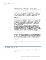
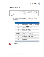
Figure 2-3
SVP Server Front Panel
On-screen elements on the SVP Server Front Panel are described
in
Table 2-4
.
Table 2-4
SVP Server Front Panel Features
Feature
Descriptions
RS-232 Port
A male DB-9 connector (DTE) used for RS-232 connection to a
terminal, terminal emulator, or modem for system administration.
Link LEDs
LNKOK
Lit when there is a network connection.
ACT
Lit if there is system activity.
COL
Lit if there are network collisions.
NETWORK
Connects to wired (Ethernet) LAN.
ERROR LED
Lit when the system has detected an error.
STATUS LEDs: Indicate system error messages and status.
1
Heartbeat: indicates gateway is running.
2
Indicates active calls.
3, 4, 5
Currently unused.
PWR (power jack)
Connects to the AC adapter supplying power to the system.
CAUTION
Use only the Class II AC Adapter with output 24VDC, 1A, provided by NEC Business
Solutions Ltd.
Summary of Contents for SVP SERVER -
Page 2: ......
Page 8: ...iv Contents SVP Server Installation Setup Maintenance Manual Revision 1 ...
Page 10: ...vi Figures SVP Server Installation Setup Maintenance Manual Revision 1 ...
Page 12: ...viii Tables SVP Server Installation Setup Maintenance Manual Revision 1 ...
Page 16: ...1 4 Introduction SVP Server Installation Setup Maintenance Manual Revision 1 ...
Page 26: ...2 10 SVP Server Overview SVP Server Installation Setup Maintenance Manual Revision 1 ...
Page 30: ...3 4 Installing the SVP Server SVP Server Installation Setup Maintenance Manual Revision 1 ...
Page 54: ...Index 2 SVP Server Installation Setup Maintenance Manual Revision 1 ...


