En-24
Option1 Settings Menu
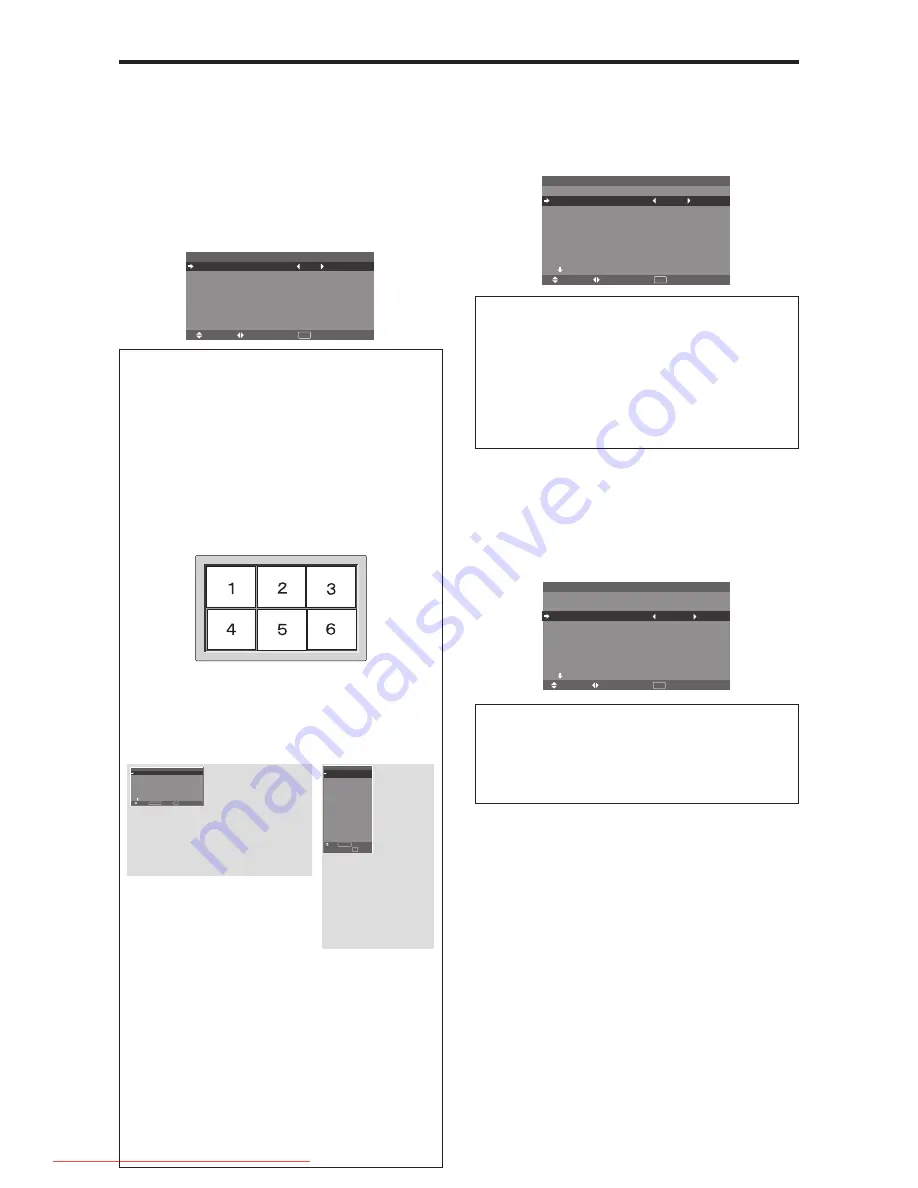
Setting the on-screen menu
This sets the position of the menu, the display format
(horizontal or vertical) etc.
Example: Turning the DISPLAY OSM off
On “OPTION1” menu, select “OSM”, then press the MENU/
ENTER button.
The “OSM” menu appears.
On “DISPLAY OSM” of “OSM” menu, select “OFF”.
SEL.
ADJ.
RETURN
O S M
EXIT
D I S P L AY O S M
O S M A D J .
O S M A N G L E
O S M O R B I T E R
O S M C O N T R A S T
: O F F
: 1
: H
: O F F
: L O W
Information
䡵
DISPLAY OSM settings
ON:
The informations on screen size, volume control,
etc. will be shown.
OFF:
The informations on screen size, volume control,
etc. will not be shown.
The DISPLAY button on the remote control will not
function either.
䡵
OSM ADJUST settings
Adjusts the position of the menu when it appears on the screen.
The position can be set between 1 to 6.
䡵
OSM ANGLE settings
Sets the display format (landscape “H” or portrait “V”).
When the unit is installed vertically set the OSM
ANGLE at “V”.
“H”
“V”
SEL.
RETURN
O P T I O N 1
1 / 4
O S M
B N C I N P U T
D - S U B I N P U T
R G B S E L E C T
H D S E L E C T
I N P U T S K I P
A L L R E S E T
N E X T PA G E
: R G B
: R G B
: A U TO
: 1 0 8 0 B
: O F F
: O F F
EXIT
MENU/ENTER
OK
* The menu language for “V” is English only.
* Some menu items including LONG LIFE mode will
not be displayed with “V”, but can be performed by
setting with “H” (See pages 19 and 20 for the menu
items that can be displayed with “V”).
䡵
OSM ORBITER settings
ON:
The position of the menu will be shifted by eight
dots each time OSM is displayed.
OFF:
OSM will be displayed at the same position.
䡵
OSM CONTRAST settings
NORMAL:
OSM brightness is set to normal.
LOW:
OSM brightness is set to lower.
: R G B
: R G B
: AU TO
: 1 0 8 0 B
: O F F
: O F F
1024
ⴒ
768
EXIT
SEL.
RETURN
MENU/ENTER
OK
O P T I O N 1
O S M
B N C I N P U T
D - S U B I N P U T
R G B S E L E C T
H D S E L E C T
I N P U T S K I P
A L L R E S E T
Setting the BNC input connector type
Select whether to set the input of the 5 BNC connectors to
RGB, Component or SCART1,2.
Example: Set the “BNC INPUT” mode to “COMP.”
On “BNC INPUT” of “OPTION1” menu, select “COMP.”.
SEL.
ADJ.
RETURN
O P T I O N 1
1 / 4
O S M
B N C I N P U T
D - S U B I N P U T
R G B S E L E C T
: AU TO
H D S E L E C T
I N P U T S K I P
A L L R E S E T
N E X T PAG E
: C O M P.
: R G B
: 1 0 8 0 B
: O F F
: O F F
EXIT
Information
䡵
BNC INPUT Settings
RGB:
Use the 5BNC terminals for RGB input.
COMP.:
Use the 3BNC terminals for component input.
SCART1:
Use the 4BNC terminals for RGB with
composite sync. See page En-9.
SCART2:
Use the 3BNC terminals for RGB and the
VIDEO1 terminal for composite sync. See page En-9.
Setting the RGB1 connector
Select one of the signals being transmitted to the RGB1
terminal.
Example: Set the “D-SUB INPUT” mode to “SCART3”
On “D-SUB INPUT” of “OPTION1” menu, select
“SCART3”.
O P T I O N 1
1 / 4
O S M
B N C I N P U T
D - S U B I N P U T
R G B S E L E C T
: AU TO
H D S E L E C T
I N P U T S K I P
A L L R E S E T
N E X T PAG E
: R G B
: S C A RT 3
: 1 0 8 0 B
: O F F
: O F F
SEL.
ADJ.
RETURN
EXIT
Information
䡵
D-SUB INPUT Settings
RGB:
Use the D-SUB terminal for RGB input.
SCART3:
Use the D-SUB terminal for RGB signal fed
from SCART. See page En-9.
Downloaded From TV-Manual.com Manuals


