background image

45

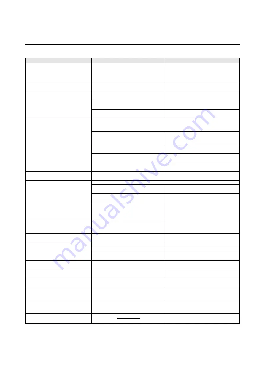
Picture is disturbed.
Sound is noisy.
Remote control unit operates errone-
ously.
The remote controller does not work.

Monitor’s power does not turn on when
the remote controller’s power button is
pressed.

Monitor does not operate when the re-
mote controller’s buttons are pressed.

No sound or picture is produced.

Picture appears but no sound is pro-
duced.

Poor picture with VIDEO signal input.

Poor picture with RGB signal input.

Tint is poor or colors are weak.

Nothing appears on screen.

Part of picture is cut off or picture is not
centered.
Image is too large or too small.

Picture is unstable.

POWER/STANDBY indicator is lighted
in orange or red.

POWER/STANDBY indicator is blinking
in red.

POWER/STANDBY indicator is blinking
in green.

• Is a connected component set directly in

front or at the side of the display?

• Are the remote controller’s batteries worn

out?

• Is the monitor’s power cord plugged into

a power outlet?

• Are all the monitor’s indicators off?

• Are the remote controller’s batteries worn

out?

• Is the remote controller pointed at the

monitor, or is there an obstacle between
the remote controller and the monitor?

• Is direct sunlight or strong artificial light

shining on the monitor’s remote control
sensor?

• Are the remote controller’s batteries worn

out?

• The remote cable is plugged into the

REMOTE IN terminal (Wired)

• The front panel buttons of the main unit

do not function.

• Is the monitor’s power cord plugged into

a power outlet?

• Is the volume set at the minimum?
• Is the mute mode set?
• Are the speakers properly connected?
• Is AUDIO INPUT set correctly?

• Improper control setting.

Local interference.
Cable interconnections.
Input impedance is not correct level.

• Improper control setting.

Incorrect 15 PIN connector pin
connections.

• Are the tint and colors properly adjusted?

• Is the computer’s power turned on?
• Is a source connected?
• Is the power manager function in the

standby or off mode?

• Is the position adjustment appropriate?

• Is the screen size adjustment appropri-

ate?

• Is the computer’s resolution setting

appropriate?

• Horizontal and / or vertical sync signal is

not present when the Intelligent Power
Manager control is on.

• The temperature inside the main unit has

become too high and has activated the
protector.

Troubleshooting

If the picture quality is poor or there is some other problem, check the adjustments, operations, etc., before requesting service.

• Leave some space between the display and

the connected components.

• Replace both batteries with new ones.

• Plug the monitor’s power cord into a power

outlet.

• Press the power button on the monitor to

turn on the power.

• Replace both batteries with new ones.

• Point the remote controller at the monitor’s

remote control sensor when pressing but-
tons, or remove the obstacle.

• Eliminate the light by closing curtains, point-

ing the light in a different direction, etc.

• Replace both batteries with new ones.

• Unplung the remote cable from the monitor.

• The front panel buttons do not function

during Control Lock.

• Plug the monitor’s power cord into a power

outlet.

• Increase the volume.
• Press the remote controller’s mute button.
• Connect the speakers properly.
• Set AUDIO INPUT on the OPTION menu

correctly.

• Adjust picture control as needed.

Try another location for the monitor.
Be sure all connections are secure.

• Adjust picture controls as needed.

Check pin assignments and connections.

• Adjust the tint and color (under “PICTURE”).

• Turn on the computer’s power.
• Connect source to the monitor.
• Operate the computer (move the mouse, etc.).

• Adjust the “SCREEN” properly.

• Press the “WIDE” button on the remote

controller and adjust properly.

• Set to the proper resolution.

• Check the input signal.

• Promptly switch off the power of the main

unit and wait until the internal temperature
drops. See*1.

• Prompty switch off the power of the main

unit. See *2.

Symptom

Checks

Remedy

*1 Overheat protector

If the monitor becomes too hot, the overheat protector will be activated and the monitor will be turned off. If this happens., turn off the power to the
monitor and unplug the power cord. If the room where the monitor is installed is particularly hot, move monitor to a cooler location and wait for the
monitor to cool for 60 minutes. If the problem persists, contact your NEC dealer for service.

*2 In the following case, power off the monitor immediately and contact your dealer or authorized NEC Center.

The monitor turns off 5 seconds after powering on and then the POWER/STANDBY indicator blinks. It indicators that the power supply circuit or,
one more fans have been damaged.

Summary of Contents for PlasmaSync 42MP1

Page 1: ...NEC Technologies PlasmaSync Plasma Monitor User s Manual...

Page 2: ...the warranty will be void Moreover there is a serious risk of electric shock 7 Do not attempt to service or repair the unit NEC is not liable for any bodily harm or damage caused if unquali fied perso...

Page 3: ...guidelines and recommendations for minimizing the occurrence of image burn Always enable and use your computer s screen saver function during use with a computer input source Display a moving image wh...

Page 4: ...modifier le cordon d alimentation 5 D brancher l appareil pendant les temp tes ou si l appareil n est pas utilis pendant une longue p riode 6 Ne pas ouvrir le coffret Des composants de haute ten sion...

Page 5: ...ations suivantes pour minimiser l occurence de br lure d image Assurez vous de mettre en marche et d utliser l conomisateur d cran chaque fois que c est possible lorsque vous l utilisez avec une sourc...

Page 6: ...ud ing adjustment of user controls These costs are the re sponsibility of the NECTECH dealer from whom the product was purchased 3 Payment of shipping charges HOW YOU CAN GET WARRANTY SERVICE 1 To obt...

Page 7: ...hing computer images with a wide screen 15 OSM Controls 16 Menu Operations 16 Picture Settings Menu 18 Adjusting the picture 18 Setting the picture mode according to the brightness of the room 19 Sett...

Page 8: ...A As it is laid down with the screen face down See Draw ing B Lay the protective sheet which was wrapped around the monitor when it was packaged beneath the screen surface so as not to scratch the sc...

Page 9: ...and HDTV signal compatibility PCs VCRs Laser Disc and DVD player source compat ibility AccuBlend scan conversion automatically converts VGA SVGA and SXGA signals to the panel s native resolution RGB...

Page 10: ...mode 3 LEFT and RIGHT Enlarges or reduces the image Functions as the CURSOR buttons in the On screen display OSM mode 4 INPUT SELECT EXIT Switches the input in the following order VIDEO1 VIDEO2 RGB3...

Page 11: ...rminal is used when power ON OFF input se lection andAUDIO MUTE and other controls are oper ated externally by external control See also page 36 for external control C REMOTE CONTROL Connect the suppl...

Page 12: ...s follows each time the button is pressed VIDEO1 VIDEO2 RGB3 RGB2 RGB1 VIDEO3 DVD HD 4 DVD HD Press this button to select DVD HD as the source DVD HD can also be selected using the INPUT SE LECT butto...

Page 13: ...using the supplied remote control unit in the wired condition F Remote control signal transmitter Transmits the remote control signals Battery Installation and Replacement Insert the 2 AAA batteries m...

Page 14: ...of about 7 m 23ft from the front of the monitor s remote control sen sor and at a horizontal angle of within 30 The remote control operation may not function if the monitor s remote control sensor is...

Page 15: ...VIDEO 2 VIDEO 3 Installation Document Camera VCR or Laser Disc Player DVD Player Signal cable supplied To Mini D Sub 15 pin connector on the plasma monitor Monitor adapter for Macintosh supplied IBM...

Page 16: ...IN DVI connector of the main unit Note that the RGB3 IN DVI terminal does not support analog RGB input source Note 1 Input TMDS signals conforming to DVI standards The TMDS input corresponds to 1 lin...

Page 17: ...itor 1 Strip the ends of the speaker wires 2 Press down the tabs below the SPEAKERS terminals insert the speaker wire and release the tab to secure the speaker wire connection a Connect the right spea...

Page 18: ...9 Signal Digital T M D S Data 2 T M D S Data 2 T M D S Data 2 Shield No connection No connection DDC Clock DDC Data No connection T M D S Data 1 T M D S Data 1 T M D S Data 1 Shield No connection No c...

Page 19: ...n on the remote controller or the unit to decrease to the desired level MUTE To cancel the sound Press the MUTE button on the remote controller to cancel sound press again to restore DISPLAY To check...

Page 20: ...s the OFF TIMER button once 2 The remaining time is displayed then turns off after a few seconds 3 When five minutes remain the remaining time appears until it reaches zero O F F T I M E R 3 0 OFF TIM...

Page 21: ...is displayed The picture has the same size as video pictures with a 4 3 aspect ratio FULL size screen The image is expanded in the horizontal direction Images compressed in the horizontal direction s...

Page 22: ...al direction When using a graphic accelerator board that is capable of displaying 848 480 FULL size screen Information Supported resolution See page 44 for details on the display output of the various...

Page 23: ...ed with respect to the screen as shown on the diagram Depending on the screen s mode the OSM may be dis played slightly differently In the explanation the OSM section is shown close up MAIN MENU PICTU...

Page 24: ...display is displayed OSM ADJ Adjusts the vertical and horizontal positions of the menu display POWER MGT Sets the monitor for use as an energy saving display when used with a computer GRAY LEVEL In ca...

Page 25: ...vious screen reappears 5 Once the adjustment is completed Press the EXIT button to return to the main menu To delete the main menu press the EXIT button once more Note If CAN NOT ADJUST appears When t...

Page 26: ...Set this mode when watching video in a dark room This mode provides darker finer pic tures like the screen in movie theaters CONTRAST 80 for RESET mode BRIGHTNESS 95 for RESET mode NORMAL Set this mo...

Page 27: ...when the and buttons are pressed 1 2 3 PRO See page 21 to set PRO P I C T U R E CONTRAST BRIGHTNESS SHARPNESS COLOR TINT PICTURE MODE COLOR TEMP NR MEMORY 1 NR 2 R G SEL ADJ RETURN EXIT Information S...

Page 28: ...rs 4 Press the PROCEED button The WHITE BALANCE screen appears 5 Use the and buttons to select RED GAIN W H I T E B A L A N C E GAIN RED GREEN BLUE BIAS RED GREEN BLUE SEL ADJ RETURN EXIT R GAIN 6 Adj...

Page 29: ...ther the or button is pressed within 5 sec onds the current selection is set and the previous screen reappears 5 Once the setting is completed Press the EXIT button to return to the main menu To delet...

Page 30: ...o delete the main menu press the EXIT button once more NOTE If CAN NOT ADJUST appears Set AUDIO INPUT on the OPTION menu correctly Information Sound settings menu BASS Changes the level of low frequen...

Page 31: ...epeat from step 3 5 Press the PROCEED button The vertical position of the computer s image has now been adjusted 4 Adjust using the and buttons 2 To adjust the normal mode Use the and buttons to selec...

Page 32: ...he on screen display When using the monitor for presentations etc the moni tor can be set so that the input source screen mode etc do not appear Example Turning the on screen display mode off Press th...

Page 33: ...nd buttons OSM OSM ADJ POWER MGT GRAY LEVEL PLE CINEMA MODE RESET ON 1 OFF 3 AUTO AUTO SEL ADJ RETURN EXIT F U N C T I O N F U N C T I O N OSM OSM ADJ POWER MGT GRAY LEVEL PLE INVERSE CINEMA MODE RESE...

Page 34: ...efault settings Select RESET under the function menu Note that this also restores other settings to the factory defaults 3 To turn the power management function on Use the and buttons to select ON The...

Page 35: ...han from the standby mode Operate the keyboard or mouse The pic ture reappears but more time is required than from the standby mode or suspend mode Horizontal and vertical synchronizing sig nals are p...

Page 36: ...OSM OSM ADJ POWER MGT GRAY LEVEL PLE INVERSE CINEMA MODE RESET ON 1 OFF 9 AUTO AUTO SEL ADJ RETURN EXIT Setting the brightness level to the minimum Locking this mode allows you to dim the picture Exa...

Page 37: ...faults F U N C T I O N OSM OSM ADJ POWER MGT GRAY LEVEL PLE INVERSE CINEMA MODE RESET ON 1 OFF 3 AUTO AUTO SEL ADJ RETURN EXIT F U N C T I O N OSM OSM ADJ POWER MGT GRAY LEVEL PLE INVERSE CINEMA MODE...

Page 38: ...GB3 ADJ RGB1 VIDEO1 HD DVD1 COMP RGB 1080B 1 SEL ADJ RETURN EXIT Setting the allocation of the audio connectors Setting the AUDIO 1 2 and 3 connectors to the desired input Example Set AUDIO 1 to RGB 2...

Page 39: ...80 line signal with a horizontal frequency of 31 72 KHz is in put the image may be compressed hori zontally To prevent this set RGB SELECT to WIDE DTV Set this model when watching digital broad castin...

Page 40: ...ETURN EXIT Adjusting the display position in the RGB3 input mode If the image is not stable when in the RGB3 input mode switch the RGB3 ADJ number to 2 or 3 Example Setting the 1 mode to 2 Press the P...

Page 41: ...CEED button The display language is switched to Deutsch 5 Once the setting is completed Press the EXIT button to return to the main menu To delete the main menu press the EXIT button once more LANGUAG...

Page 42: ...8 NTSC Information Video signal formats Different countries use different formats for video sig nals Set to the format used in your current country AUTO1 2 The video signals are automatically de tecte...

Page 43: ...nections are made as described below 2 Connector on the external equipment side Serial port RS 232C connector See the specifications of the equipment that is to be connected for the type of connector...

Page 44: ...mmand 1 Unit ID 1 and 2 Command 2 Data Length and Data Check Sum Example DFH 80H 60H 47H 01H 01H 08H Command 1 Unit ID 1 Unit ID 2 Command 2 Data Length Data Check Sum Total 208H 2 Error Processing Wh...

Page 45: ...ol equipment switches off the power of the plasma monitor Transmission Data 9FH 80H 60H 4FH 00H CKS ACK The plasma monitor returns the following ACK when the power is switched off 3FH 60H 80H 4FH 00H...

Page 46: ...Screen display On 02H Screen display Off ACK 7FH 60H 80H 58H 01H DATA00 CKS DATA00 01H Screen display On 02H Screen display Off Screen display On Off is equivalent to the screen display On Off functi...

Page 47: ...DATA00 USER PICTURE Gain Flag 01H DATA01 BRIGHT Gain Flag 08H DATA02 BRIGHT Gain E0H 32 FFH 01 00H 0 01H 01 20H 32 ACK 7FH 60H 80H 7FH 02H DATA00 DATA01 CKS DATA00 USER PICTURE Gain Flag 01H DATA01 BR...

Page 48: ...sion Data DFH 80H 60H 7FH 04H DATA00 to DATA03 CKS DATA00 USER PICTURE Gain Flag 01H DATA01 GREEN Gain Flag 02H DATA02 GREEN Gain 1 Bias D8H 40 FFH 1 00H 0 28H 40 DATA03 GREEN Gain2 Drive D8H 40 FFH 1...

Page 49: ...1 00H 0 28H 40 DATA02 BLUE Gain Bias D8H 40 FFH 1 00H 0 28H 40 DATA03 COLOR Gain EAH 22 FFH 01 00H 0 01H 01 16H 22 DATA04 TINT Gain EAH 22 FFH 01 00H 0 01H 01 16H 22 DATA05 SHARPNESS Gain F0H 16 FFH 0...

Page 50: ...rns the following ACK 7FH 60H 80H 6FH 03H DATA00 DATA01 DATA02 CKS DATA00 AUDIO 1 DATA01 AUDIO 2 DATA02 AUDIO 3 VISUAL INPUT DATA 01H Video 1 02H Video 2 03H Video 3 05H HD HD1 or DTV or DTV 1 06H HD2...

Page 51: ...located at the center 2 Only when using a graphic accelerator board that is capable of displaying 848 480 3 Aspect ratio is 5 4 This signal is converted to a 600 dots 480 lines signal NOTE With digita...

Page 52: ...re inside the main unit has become too high and has activated the protector Troubleshooting If the picture quality is poor or there is some other problem check the adjustments operations etc before re...

Page 53: ...W 648 H 89 D mm 70 6 lbs 32 kg 0 C to 40 C 32 F to 104 F 20 to 80 0 to 1900m 0 to 6230ft 10 C to 50 C 14 F to 122 F 10 to 90 0 to 3000m 0 to 9840ft Power on off Input source select Volume up down OSM...

Page 54: ...NEC Technologies Inc 1250 N Arlington Heights Road Suite 500 Itasca Illinois 60143 1248 Printed in Japan 78411092 Printed on recycled paper...

Reviews: