ADJUSTMENTS
PROCEDURES
15.
Video
D/A
Control
Setting
(1)
Connect
the
wire
between
pin
1
and
pin
7
of
connector
JB
on
pCOMA/
PWB
(PWC-3839)
[TEST
MODE].
(2)
Input
the
NTSC
1/4
window
white
signal,
terminated
at
75Q.
(3)
Connect
your
scope
probe
to
the
V-CRT
B
cathode.
Use
the
Remote
Control
CONTRAST
Up/Down
but
tons
and
verify
that
the
video
white
to
black
swing
equals
85Vp-p.
If
this
swing
is
less
than
80Vp-p.
Adjust
RGB
I/O
PWB
VR872
(SUB
BRIGHT)
to
desired
level
is
attained.
Note;
Do
NOT
use
the
Remote
Control
BRIGHT
key
to
perform
this
step.
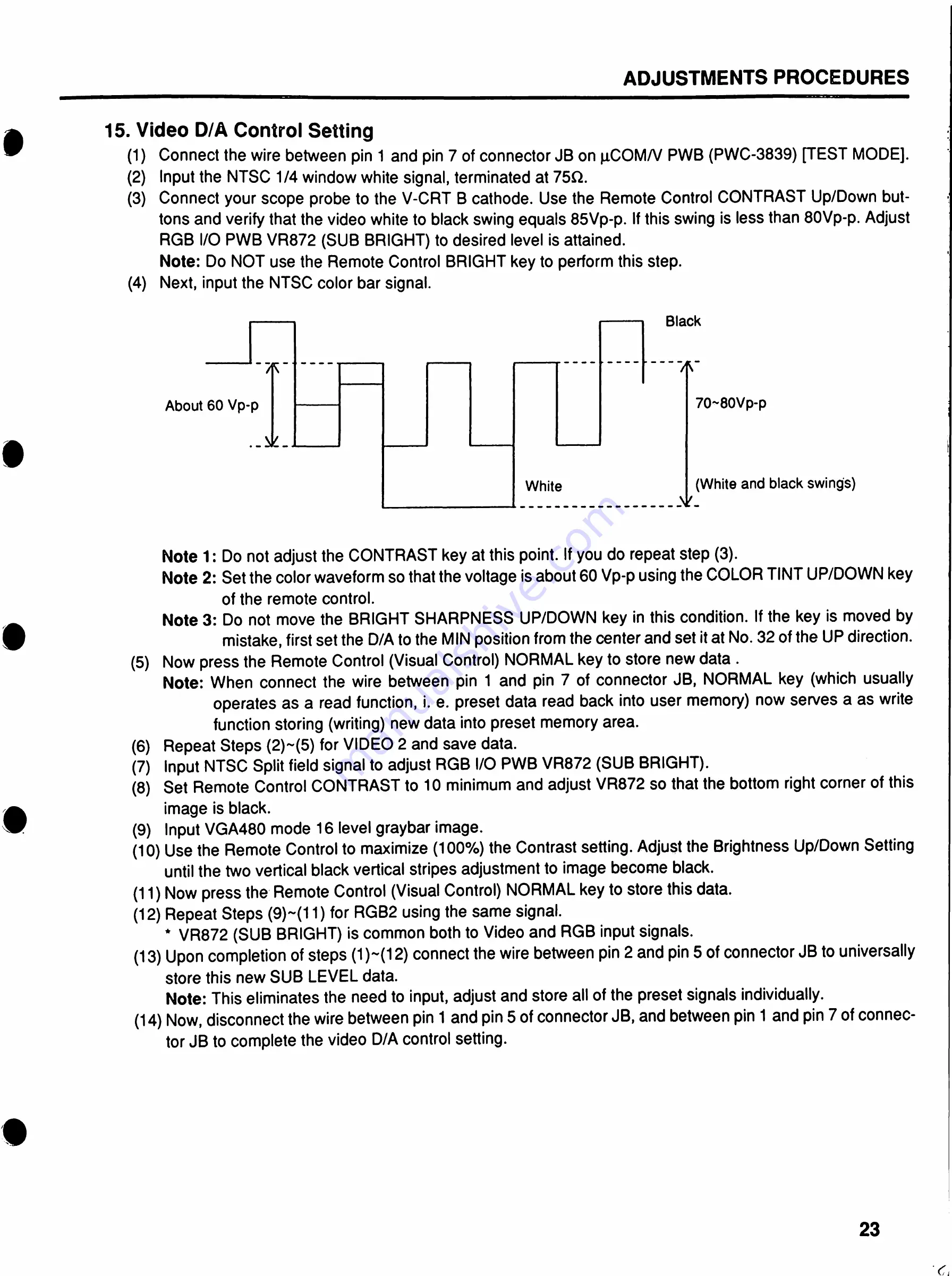
(4)
Next,
input
the
NTSC
color
bar
signal.
Black
71^
70~80Vp-p
About
60
Vp-p
§
(White
and
black
swings)
White
.Nir.
Note
1
:
Do
not
adjust
the
CONTRAST
key
at
this
point.
If
you
do
repeat
step
(3).
Note
2:
Set
the
color
waveform
so
that
the
voltage
is
about
60
Vp-p
using
the
COLOR
TINT
UP/DOWN
key
of
the
remote
control.
Note
3:
Do
not
move
the
BRIGHT
SHARPNESS
UP/DOWN
key
in
this
condition.
If
the
key
is
moved
by
mistake,
first
set
the
D/A
to
the
MIN
position
from
the
center
and
set
it
at
No.
32
of
the
UP
direction.
(5)
Now
press
the
Remote
Control
(Visual
Control)
NORMAL
key
to
store
new
data
.
Note:
When
connect
the
wire
between
pin
1
and
pin
7
of
connector
JB,
NORMAL
key
(which
usually
operates
as
a
read
function,
i.
e.
preset
data
read
back
into
user
memory)
now
serves
a
as
write
function
storing
(writing)
new
data
into
preset
memory
area.
(6)
Repeat
Steps
(2)~(5)
for
VIDEO
2
and
save
data.
(7)
Input
NTSC
Split
field
signal
to
adjust
RGB
I/O
PWB
VR872
(SUB
BRIGHT).
(8)
Set
Remote
Control
CONTRAST
to
10
minimum
and
adjust
VR872
so
that
the
bottom
right
corner
of
this
image
is
black.
(9)
Input
VGA480
mode
16
level
graybar
image.
(10)
Use
the
Remote
Control
to
maximize
(100%)
the
Contrast
setting.
Adjust
the
Brightness
Up/Down
Setting
until
the
two
vertical
black
vertical
stripes
adjustment
to
image
become
black.
(11)
Now
press
the
Remote
Control
(Visual
Control)
NORMAL
key
to
store
this
data.
(12)
Repeat
Steps
(9)~(11)
for
RGB2
using
the
same
signal.
*
VR872
(SUB
BRIGHT)
is
common
both
to
Video
and
RGB
input
signals.
~(12)
connect
the
wire
between
pin
2
and
pin
5
of
connector
JB
to
universally
(13)
Upon
completion
of
steps
(1)
store
this
new
SUB
LEVEL
data.
Note:
This
eliminates
the
need
to
input,
adjust
and
store
all
of
the
preset
signals
individually.
(14)
Now,
disconnect
the
wire
between
pin
1
and
pin
5
of
connector
JB,
and
between
pin
1
and
pin
7
of
connec
tor
JB
to
complete
the
video
D/A
control
setting.
23
Summary of Contents for PG-2740
Page 41: ...I I f ...


