background image

English

English-9

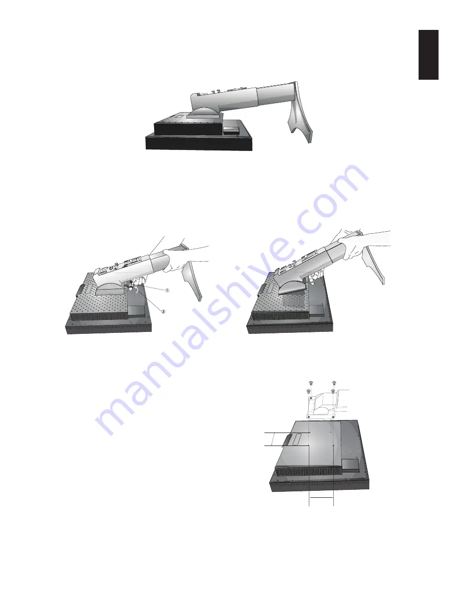
Figure S.1

4. Place one hand around the base and one hand on the Quick Release Lever. Move the Quick Release Lever in the direction

indicated by the arrows (

Figure S.2

).

5. Lift up the bottom of the stand to unhook it from the monitor (

Figure S.3

). The monitor can now be mounted using and

alternate method. Reverse process to reattach stand.

NOTE:

Use only VESA-compatible alternative mounting method (100 mm pitch).

NOTE:

Handle with care when removing monitor stand.

Figure S.2

Flexible Arm Installation

This LCD monitor is designed for use with a flexible arm.

1. Follow the instructions on how Remove Monitor Stand for

Mounting to remove the stand.

2. Change the 4 screws that were removed from the stand removal to

attach the flexible arm to the monitor (

Figure F.1

).

Caution:

• When mounting, use ONLY the screws (4 pcs) that were

removed from the stand to avoid damage to the monitor
or stand.

• The monitor should only be used with an approved arm

(e.g. GS mark).

• When using mounting accessories (e.g. VESA (100 x 100),

use M4 size screws (Length: bracket thi 10mm).
Recommended Fasten Force: 98 - 137N•cm.

• To avoid blocking vent, keep adequate space above and

behind the monitor when using with flexible arm.

NOTE:

The mounting stand must be able to sustain at least 24.4 kg
and be UL certified.

Figure S.3

Remove Monitor Stand for Mounting

To prepare the monitor for alternate mounting purposes:

1. Disconnect all cables.

2. Place hands on each side of the monitor and lift up to the highest position.

3. Place monitor face down on a non-abrasive surface (

Figure S.1

).

100mm

100mm

Figure F.1

Up

Slide

Weight of LCD assembly: 6.1 kg MAX

Summary of Contents for P221W-BK-SV - MultiSync - 22" LCD Monitor

Page 1: ...MultiSync P221W User s Manual ...

Page 2: ...nglish 3 Contents English 5 Quick Start English 6 Controls English 10 Specifications English 14 Features English 15 Troubleshooting English 16 Appendix English 17 Using the Auto Brightness function English 20 TCO 03 English 21 Manufacturer s Recycling and Energy Information English 22 ...

Page 3: ... COMPONENTS INSIDE REFER SERVICING TO QUALIFIED SERVICE PERSONNEL Declaration of the Manufacturer We hereby certify that the colour monitor MultiSync P221W L227HT is in compliance with Council Directive 2006 95 EC EN 60950 1 Council Directive 2004 108 EC EN 55022 EN 61000 3 2 EN 61000 3 3 EN 55024 and marked with NEC Display Solutions Ltd 4 13 23 Shibaura Minato Ku Tokyo 108 0023 Japan CAUTION Ple...

Page 4: ... receiver is connected Consult your dealer or an experienced radio TV technician for help If necessary the user should contact the dealer or an experienced radio television technician for additional suggestions The user may find the following booklet prepared by the Federal Communications Commission helpful How to Identify and Resolve Radio TV Interference Problems This booklet is available from t...

Page 5: ... Immediately unplug your monitor from the wall outlet and refer servicing to qualified service personnel under the following conditions When the power supply cord or plug is damaged If liquid has been spilled or objects have fallen into the monitor If the monitor has been exposed to rain or water If the monitor has been dropped or the cabinet damaged If the monitor does not operate normally by fol...

Page 6: ... image persistence after image effects Get regular eye checkups Ergonomics To realize the maximum ergonomics benefits we recommend the following Adjust the Brightness until the background raster disappears Do not position the Contrast control to its maximum setting Use the preset Size and Position controls with standard signals Use the preset Colour Setting Use non interlaced signals with a vertic...

Page 7: ...s Manual CD ROM Cable Cover Screw 4 M4 x 14 to mount the monitor to a flexible arm page 9 Power Cord User s Manual DVI D to DVI D cable Cable Cover CD ROM 15 pin mini D SUB male to 15 pin mini D SUB male Screws Remember to save your original box and packing material to transport or ship the monitor User s Manual NOTE This monitor can be equipped with optional loudspeakers MultiSync Sound bar Pleas...

Page 8: ... to the highest position Figure C 1 4 Connect all cables to the appropriate connectors Figure C 1 NOTE Incorrect cable connections may result in irregular operation damage display quality components of LCD module and or shorten the module s life 5 To keep the cables neatly organized place them into the cable management system that is built into the stand Place the power cable into the specific hoo...

Page 9: ...inlet must be turned on Turn on the monitor with the front power button Figure E 1 and the computer NOTE The Vacation Switch is a true on off switch If this switch is on the OFF position the monitor cannot be turned on using the front button DO NOT switch on off repeatedly 10 No touch auto adjust automatically adjusts the monitor to optimal settings upon initial setup for most timings For further ...

Page 10: ... raise the screen place hands on each side of the monitor and lift up to the highest position Figure RL 1 To rotate screen place hands on each side of the monitor screen and turn clockwise from Landscape to Portrait or counter clockwise from Portrait to Landscape Figure R 1 To rotate OSD menu between landscape and portrait refer to Controls section Figure R 1 Figure RL 1 Raise and Lower Monitor Sc...

Page 11: ...tand removal to attach the flexible arm to the monitor Figure F 1 Caution When mounting use ONLY the screws 4 pcs that were removed from the stand to avoid damage to the monitor or stand The monitor should only be used with an approved arm e g GS mark When using mounting accessories e g VESA 100 x 100 use M4 size screws Length bracket thickness 10mm Recommended Fasten Force 98 137N cm To avoid blo...

Page 12: ...make adjustments to various settings resulting in a more comfortable viewing experience Do not cover this sensor Turns the monitor on and off Indicates that the power is on Can be changed between blue and green in the Advanced OSD Control menu Enters OSD sub menus Changes the input source when not in the OSD Control menu Opens OSD control menu Exits the OSD sub menu Exits OSD Control menu Navigate...

Page 13: ... not give you a satisfactory picture setting a further tuning can be performed using the H Size or V Size function dot clock For this a Moiré test pattern could be used This function may alter the width of the picture Use Left Right Menu to center the image on the screen If the H Size or V Size is wrongly calibrated the result would look like on the left drawing The image should be homogeneous FIN...

Page 14: ... on the PC and Video card used or when another Video signal cable is attached this function may not operate VIDEO DETECT Selects the method of video detection when more than one computer is connected FIRST The video input has to be switched to FIRST mode When current video input signal is not present then the monitor searches for a video signal from the other video input port If the video signal i...

Page 15: ...T with no control To activate the OSD Lock Out function press SELECT then Right button and hold down simultaneously To deactivate the OSD Lock Out press SELECT then Right button and hold down simultaneously while in the OSD menu No controls can be adjusted while in the lock out mode OSD LOCK OUT with BRIGHTNESS only control To activate the OSD Lock Out function press SELECT then Down and Left butt...

Page 16: ...S cites 1440 x 1050 1 at 60 Hz to 75 Hz recommended resolution at 60 Hz for 1680 x 1050 at 60 Hz optimal display performance Active Landscape Horiz 474 mm 18 7 inches Display Area Vert 296 mm 11 7 inches Portrait Horiz 296 mm 11 7 inches Vert 474 mm 18 7 inches Power Supply AC 100 240 V 50 60 Hz Current Rating 0 95 0 40 A with Option Dimensions Landscape 506 4 mm W x 410 560 mm H x 247 3 mm D 19 9...

Page 17: ...s tilt base for preferred angle of vision small footprint and compliance with MPRII and TCO guidelines for lower emissions Plug and Play The Microsoft solution with the Windows operating system facilitates setup and installation by allowing the monitor to send its capabilities such as screen size and resolutions supported directly to your computer automatically optimizing display performance IPM I...

Page 18: ...nitor when not in use Message OUT OF RANGE is displayed screen is either blank or shows rough images only Image is displayed only roughly pixels are missing and OSD warning OUT OF RANGE is displayed Either signal clock or resolution is too high Choose one of the supported modes OSD warning OUT OF RANGE is displayed on a blank screen Signal frequency is out of range Choose one of the supported mode...

Page 19: ...tness level of your environment and adjusting the monitor with your BRIGHTNESS setting NOTE Do not cover environmental brightness sensor Ambibright sensor Black Level Allows you to manually adjust the black level Press Left or Right to adjust LOW BRIGHTNESS ON Reduces the brightness level OFF Default setting Tag2 Auto Adjust Automatically adjusts the Image Position and H Size settings and Fine set...

Page 20: ...uter is connected Press Left or Right to select FIRST The video input has to be switched to FIRST mode When current video input signal is not present then the monitor searches for a video signal from the other video input port If the video signal is present in the other port then the monitor switches the video source input port to the new found video source automatically The monitor will not look ...

Page 21: ...and CONTRAST can be adjusted while in the lock out mode OSD LOCK OUT with no control To activate the OSD Lock Out function press SELECT then Right button and hold down simultaneously To deactivate the OSD Lock Out press SELECT then Right button and hold down simultaneously while in the OSD menu No controls can be adjusted while in the lock out mode OSD LOCK OUT with BRIGHTNESS only control To acti...

Page 22: ...l Figure 2 2 Set the DARK level This is the level of brightness that the monitor will go down to when the ambient light level is low Make sure the room is at its darkest when setting this level Then use the front buttons to move the cursor up to the BRIGHTNESS setting Choose the desired brightness level Figure 3 Figure 1 Figure 2 Figure 3 When the Auto Brightness function is enabled the Brightness...

Page 23: ...ergy Energy saving mode after a certain time beneficial both for the user and the environment Electrical safety Emissions Electromagnetic fields Noise emissions Ecology The product must be prepared for recycling and the manufacturer must have a certified environmental management system such as EMAS or ISO 14 001 Restrictions on chlorinated and brominated flame retardants and polymers heavy metals ...

Page 24: ... www nec display com in Japan or http www necdisplay com in USA Energy Saving This monitor features an advanced energy saving capability When a VESA Display Power Management Signalling DPMS Standard signal is sent to the monitor the Energy Saving mode is activated The monitor enters a single Energy Saving mode Manufacturer s Recycling and Energy Information WEEE Mark European Directive 2002 96 EC ...

Reviews: