background image

10

1. Introduction

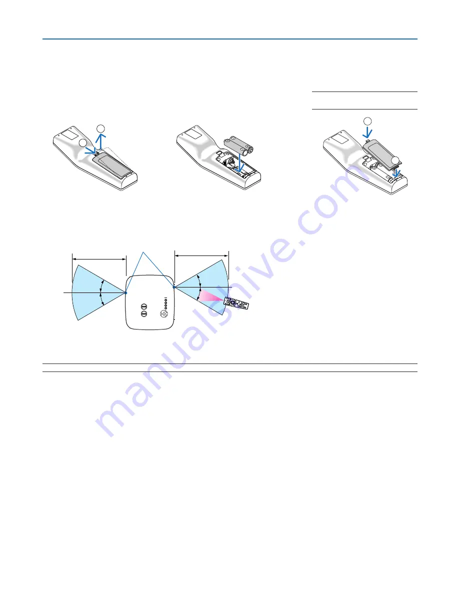
Battery Installation

1

Press  the  catch  and  re-
move the battery cover.

Install  new  ones  (AA).  Ensure 
that you have the batteries’ po-
larity (+/–) aligned correctly.

Slip the cover back over the bat-
teries until it snaps into place.

NOTE: Do not mix different types of 
batteries or new and old batteries.

NOTE: Actual operating range may differ slightly from that shown in the drawing.

TIP:

 You can determine which remote sensor on the projector is enabled in wireless mode. The options are: front, rear or both. (


page 

110

)

•  The infrared signal operates by line-of-sight up to a distance of about 22 feet/7 m and within a 60-degree angle 

of the remote sensor on the projector cabinet.

•  The projector will not respond if there are objects between the remote control and the sensor, or if strong light 

falls on the sensor.

  Weak batteries will also prevent the remote control from properly operating the projector.

Remote Control Precautions

•  Handle the remote control carefully.
•  If the remote control gets wet, wipe it dry immediately.
•  Avoid excessive heat and humidity.
•  Do not heat, take apart, or throw batteries into fire.
•  If you will not be using the remote control for a long time, remove the batteries.
•  Ensure that you have the batteries’ polarity (+/–) aligned correctly.
•  Do not use new and old batteries together, or use different types of batteries together.
•  Dispose of used batteries according to your local regulations.

Operating Range for Wireless Remote Control

2

1

2

1

7m/22 feet

7m/22 feet

remote control

remote sensor on projector cabinet

30

°

30

°

30

°

30

°

Summary of Contents for NP2150 Series

Page 1: ...LCD Projector NP3150 NP2150 NP1150 User s Manual...

Page 2: ...ark or trademark of Microsoft Corporation in the United States and or other countries VESA is a registered trademark of Video Electronics Standards Association All Rights Reserved Corel the Corel logo...

Page 3: ...HIS UNIT S PLUG WITH AN EXTENSION CORD OR IN AN OUTLET UNLESS ALL THE PRONGS CAN BE FULLY INSERTED DOC Compliance Notice for Canada only This Class B digital apparatus meets all requirements of the Ca...

Page 4: ...uch products please follow the guidance of your local authority and or ask the shop where you purchased the product After collecting the used products they are reused and recycled in a proper way This...

Page 5: ...different from that to which the receiver is connected Consult the dealer or an experienced radio TV technician for help For UK only In UK a BS approved power cable with moulded plug has a Black five...

Page 6: ...r is on Doing so can lead to melting of the cap and possibly burning your hands due to the heat emitted from the light output Do not place any objects which are easily affected by heat in front of the...

Page 7: ...ng time remove the batteries Ensure that you have the batteries polarity aligned correctly Do not use new and old batteries together or use different types of batteries together Dispose of used batter...

Page 8: ...sures Reorient or relocate the receiving antenna Increase the separation between the equipment and receiver Connect the equipment into an outlet on a circuit different from that to which the receiver...

Page 9: ...ohibited to use if certain re striction should be applied France Outdoor use limited to 10mW e i r p within the band 2454 2483 5 MHz Derogation in French overseas depart ments of Guyane and La Reunion...

Page 10: ...medical equipment Doing so may cause electromagnetic inter ference with the medical equipment possible leading to death Do not disassemble or modify the USB Wireless LAN Unit in any way Doing so coul...

Page 11: ...ions 13 Connecting Your PC or Macintosh Computer 13 Connecting an External Monitor 15 Connecting Your DVD Player with Component Output 16 Connecting Your VCR or Laser Disc Player 17 Connecting to a Ne...

Page 12: ...iting Access Level to Available Menu Items 49 L Operation Using an HTTP Browser 52 Overview 52 Preparation Before Use 52 Handling of the Address for Operation via a Browser 52 Structure of the HTTP Se...

Page 13: ...ns 81 Video 84 Sound 85 Menu Descriptions Functions Setup 86 Basic 86 Menu 91 Installation 92 Options 109 Menu Descriptions Functions Info 111 Usage Time 111 Source 1 112 Source 2 112 WIRED LAN 113 WI...

Page 14: ...e 133 Pin Assignments of D Sub COMPUTER 1 Input Connector 135 Mini D Sub 15 Pin Connector 135 Compatible Input Signal List 136 PC Control Codes and Cable Connection 137 PC Control Codes 137 Cable Conn...

Page 15: ...24FT9741 Remote control 7N900801 Batteries AA x 2 Remote Cable 7N520019 Power cable 7N080204 US 7N080011 EU VGA signal cable 7N520052 CD ROM User s manual and User Supportware 5 7N951122 7N951132 For...

Page 16: ...to allow at least 20 minutes immediately after turning on the projector and starting to display an image Also the power cable can be removed immediately after turning off the projector Auto Start elim...

Page 17: ...uthorized access adjustments and theft deterrence About this user s manual The fastest way to get started is to take your time and do everything right the first time Take a few minutes now to review t...

Page 18: ...ilter page 116 Stereo Speaker 5W x 2 AC Input Connect the supplied power cable s three pin plug here and plug the other end into an active wall outlet page 21 Main Power Switch When you plug the suppl...

Page 19: ...s connecting to video sources are disconnected before moving the projector When moving the projector or when it is not in use cover the lens with the lens cap NOTE To stand the projector on its end do...

Page 20: ...e the projector on its end 2 Pull up the carrying handle with the catch pressed down 3 Press down the left and right locks to set the carrying handle in place To place back the carrying handle press u...

Page 21: ...ge 125 4 LAMP Indicator page 118 125 5 USB Indicator Lights when a USB memory is inserted into the USB port NOTE The USB indicator will not light when non USB stor age devices such as USB mouse device...

Page 22: ...s enables you to control the projector using serial communication protocol A commercially available RS232C cross cable is required to use this port You can also control the projector by using PC Contr...

Page 23: ...3 PIP Button page 42 24 ASPECT Button page 83 25 VOLUME Buttons page 31 26 PICTURE Button page 78 80 27 PIC MUTE Button page 34 28 MAGNIFY Buttons page 34 29 LAMP MODE Button page 35 30 AUTO ADJ Butto...

Page 24: ...tor cabinet The projector will not respond if there are objects between the remote control and the sensor or if strong light falls on the sensor Weak batteries will also prevent the remote control fro...

Page 25: ...NOTE Connecting the remote cable to the REMOTE mini jack on the terminal panel will make the wireless operation unavailable WIRELESS USB LAN WIRELESS REMOTE LASER 3D REFORM AUTO ADJ ASPECT HELP PICTU...

Page 26: ...at the power cable and any other cables are disconnected before moving the projector When moving the projector or when it is not in use cover the lens with the lens cap TIP The screen sizes above are...

Page 27: ...ed back via a commercially available scan converter This is because the projector will process a video signal as a computer signal at the default setting In that case do the following When an image is...

Page 28: ...h DDWG Digital Display Working Group DVI Digital Visual Interface revision 1 0 standard The DVI D cable should be within 10 m 394 long The DVI DIGITAL connector COMPUTER 3 DVI D IN accepts VGA 640x480...

Page 29: ...l Digital signal from the COMPUTER 3 DVI D IN connector When audio equipment is connected the projector speaker is disabled When NORMAL is selected from STANDBY MODE the MONITOR OUT connector outputs...

Page 30: ...ble not supplied Component video RCA 3 cable not supplied TIP A component signal will be automatically displayed If not from the menu select Setup Options Signal Se lect Computer 1 or 2 Component When...

Page 31: ...ideo cable not supplied Video cable not supplied VCR Laser disc player Audio equipment Audio cable not supplied NOTE Refer to your VCR or laser disc player owner s manual for more information about yo...

Page 32: ...ed using the projector over a network The projector supports the Network Projector function and the Remote Desktop function of Windows Vista page 55 59 Picture transmission feature Using User Supportw...

Page 33: ...Network Type Infrastructure To make connection with a wired LAN or wireless LAN via a wireless access point you need to select the Infra structure mode From the menu select Setup Installation NETWORK...

Page 34: ...o select the Ad Hoc mode From the menu select Setup Installation Network settings WIRELESS Advanced CONNECTION NETWORK TYPE Ad Hoc The Ad Hoc mode complies with IEEE802 11 standard PC with wireless LA...

Page 35: ...and a breaker TIP The projector can be unplugged during its cool down period after it is turned off CAUTION Do not try to touch the ventilation outlet on the left front when seen from the front as it...

Page 36: ...to the projector press the Main Power switch to the on position I The projector will go into standby mode When in stand by mode the POWER indicator will light orange and the STATUS indicator will ligh...

Page 37: ...e is high the cooling fans will run for a moment and then you will get an image on the screen Immediately after turning on the projector screen flicker may occur This is normal Wait 3 to 5 minutes unt...

Page 38: ...the COMPUTER 1 2 3 COMPONENT VIDEO S VIDEO VIEWER or NETWORK buttons LASER OFF AUTO ADJ ON ASPECT LAMP MODE R CLICK L CLICK MOUSE FREEZE PIP VOLUME MAGNIFY PAGE UP DOWN SELECT POWER POWER MENU ENTER...

Page 39: ...SELEC T USB LENS SHIF T LEFT RIGH T DOW N UP WIRELESS WIRELESS LAMP STATU S POWE R ON STA ND BY SOUR CE AUTO ADJUS T 3D REFOR M SELEC T USB LENS SHIF T LEFT RIGH T DOW N UP WIRELESS WIRELESS LAMP STA...

Page 40: ...ft Vertical shift Max 0 5V Max 0 5V 1V 0 5V 0 1H 0 1H 1H Width of projected image Nomal projection position Shift to left Shift to right 1V Height of projected image NOTE The lens shift dial for LEFT...

Page 41: ...CE AUTO ADJU ST 3D REFO RM SELE CT USB LEN S SHI FT LEF T RIG HT DOW N UP WIRELESS WIRELESS LENS RELEASE Finely adjusting the size of an image Zoom lever Rotate the zoom lever to adjust the image size...

Page 42: ...djustable Tilt Foot Lever NOTE Your Keystone correction data can be reset by pressing and holding the 3D REFORM button for a minimum of 2 seconds CAUTION Do not use the tilt foot for purposes other th...

Page 43: ...ted image are parallel 1 Press the 3D REFORM button on the remote control or the projec tor cabinet The Keystone screen will be displayed on the screen 2 Press the SELECT button to select Vertical and...

Page 44: ...ing the Keystone adjustment To perform the Cornerstone adjustment press and hold the 3D REFORM button for a minimum of 2 seconds to reset the Keystone correction setting values The Key stone adjustmen...

Page 45: ...mage is enlarged by using the MAGNIFY button or when the menu is displayed NOTE Some signals may take time to display or may not be displayed correctly The Auto Adjust function does not work for compo...

Page 46: ...EFT RIGHT DOWN UP WIRELESS WIRELESS Setting the function switch There are two switches on the bottom of the battery case an applicable projector selector switch 1 and laser en able disable switch 2 Ch...

Page 47: ...y after turning on the projector and starting to display an image CAUTION Do not unplug the power cable from the wall outlet or projec tor when the projector is powered on Doing so can cause damage to...

Page 48: ...motion NOTE The image is frozen but the original video is still playing back MAGNIFY LASER 3D REFORM AUTO ADJ ASPECT HELP PICTURE PIC MUTE LAMP MODE R CLICK L CLICK MOUSE FREEZE PIP VOLUME PAGE UP DOW...

Page 49: ...Lamp Mode screen 2 Use the SELECT or button to select Eco mode 3 Press the ENTER button To cancel it press the EXIT button To change from Eco to Normal Go back to Step 2 and select Normal Re peat Step...

Page 50: ...symbol to display the NETWORK SETTINGS menu page 99 Click Mouse symbol to display the MOUSE menu Click to display a selection of the selected menu item Click to close the menu 4 Convenient Features Us...

Page 51: ...ngs 30 30 Remote mouse receiver Computer To USB port of PC or Macintosh When operating a computer via the remote mouse receiver Remote sensor on the remote mouse receiver 7m 22 feet When connecting us...

Page 52: ...ate the computer using the SELECT button with the menu displayed both the menu and the mouse pointer will be affected Close the menu and perform the mouse operation About Drag Mode By pressing the MOU...

Page 53: ...2 Project an image so that the screen is smaller than the area of the raster 3 Pick up any one of the corners and align the corner of the image with a corner of the screen The drawing shows the up pe...

Page 54: ...ORM button for a minimum of 2 seconds NOTE During 3D Reform adjustment Aspect Ratio and Screen may not be available Should this happen first reset the 3D Reform data and then do each setting Second re...

Page 55: ...button for a minimum of 2 seconds to reset the current correction data The Cornerstone function becomes available Turning on the projector will reset the previous correction setting values and correct...

Page 56: ...he main picture only To turn on PIP mode while in Picture Mute or Freeze Picture Mute and Freeze will be applied simultaneously to both the main and sub pictures The main picture signal supports the C...

Page 57: ...remote control to view a sub picture in the main picture To do so follow the steps 1 Press the PIP button on the remote control The sub picture will be displayed in the main picture Sub picture 2 Pres...

Page 58: ...ing used by unauthorized individuals Assigning a Keyword for the first time 1 Press the MENU button The menu will be displayed 2 Press the SELECT button to highlight the Setup submenu and press the EN...

Page 59: ...button to display the SECURITY SETTINGS menu 6 Press the SELECT button four times to highlight SECURITY SETTINGS and press the ENTER button The Security screen will be displayed 7 Press the SELECT bu...

Page 60: ...d Enter a keyword by using the remote control 8 1 Press the MENU button and the AUTO ADJ button to enter 1 The asterisk will be displayed in the keyword entry box 8 2 Press the MENU button and the SEL...

Page 61: ...the Main POWER switch to the off position O The projector will turn off 3 Push the Main POWER switch to the on position I The POWER indicator lights orange The projector is in standby condition 4 Pre...

Page 62: ...ighlight SECURITY SETTINGS and press the ENTER but ton The Keyword entry screen will be displayed 6 Press the ENTER button The Software keyboard will be displayed 7 Use the same procedures as steps 1...

Page 63: ...ttings available to ADVANCED and BASIC menus NOTE A user with an ADMINISTRATOR account that has no password set is registered at the factory This will allow the user to access the ACCOUNT items withou...

Page 64: ...ric characters or less case sensitive User type has two options ADVANCED and BASIC Use the software keyboard to enter a password in the NEW PASSWORD entry field A password must be 10 alphanumeric char...

Page 65: ...the ENTER button If no password is set simply press the ENTER button without entering any password 5 Change the settings and select OK Deleting a User 1 From the menu select SETUP INSTALLATION SECURIT...

Page 66: ...ctions and set up the projector and confirm that it is complete before engaging in browser op erations NETWORK SETTINGS on page 99 Operation with a browser that uses a proxy server may not be possible...

Page 67: ...screen display functions ALL OFF Cancels the muting of each of the video audio and on screen display functions PICTURE Controls the video adjustment of the projector BRIGHTNESS Increases the brightnes...

Page 68: ...connector S Video Switches to the S VIDEO IN connector Viewer Switches to the data on the USB memory device NETWORK Switches to a LAN signal PROJECTOR STATUS This displays the condition of the project...

Page 69: ...ration Environment Applicable OS Windows Vista 32 bit version Home Premium Windows Vista 32 bit version Business Windows Vista 32 bit version Ultimate Windows Vista 32 bit version Enterprise Note Thes...

Page 70: ...on press the SOURCE button The input selection window appears Another way to display the input selection window is to press the NETWORK button on the remote control The NETWORK screen will be displaye...

Page 71: ...ndows Vista 2 Click All Programs 3 Click Accessories 4 Click Connect to a Network Projector When the Permission Connect to a Network Projector window appears click Yes The Connect to a Network Project...

Page 72: ...ference If the projector cannot be found at Step 5 click Enter the projector address Then input the Network ad dress Input example http 10 32 97 61 lan and Projectorpassword Input example 82291627 dis...

Page 73: ...ual this feature is described using Windows Vista as an example but Windows XP will also work with this feature Windows XP Home Edition Service Pack 2 or later Windows XP Professional Service Pack 2 o...

Page 74: ...the Confirm new password box 9 Click Create a password The Administrator is changed to Password Protection Setting the Remote Access 1 Click Start from the desktop of Windows Vista 2 Click Control Pan...

Page 75: ...Pv4 IP Address xxx xxx xxx xxx displayed 6 Click Close 7 Click X at the upper right of the window The system goes back to the desktop Starting the Remote Desktop 1 With the projector turned on press t...

Page 76: ...Clear the check mark to display the desktop background in monochrome MENU AND WINDOW ANIMATION Clear the check mark to disable menu and window animation THEMES Clear the check mark not to use Themes...

Page 77: ...m the desktop screen projected by the projector 2 Click X on the right of the start menu The remote desktop function is stopped 3 Press the SOURCE button of the projector to select an input terminal o...

Page 78: ...n the supplied NEC User Supportware 5 CD ROM See the supplied User Supportware 5 User s Guide for installing the Ulead Photo Explorer 8 0 on your computer NOTE Use commercially available USB memory de...

Page 79: ...rom the source list An image stored in the USB memory will be displayed NOTE When SHOW THUMBNAILS is turned on in the OPTIONS menu the thumbnail screen will be displayed page 67 NOTE Pressing the EXIT...

Page 80: ...lides in a folder creation date month day year creation time hour minute second file size Number of files Indicates number of displayable slides in the selected folder The maximum number of images rec...

Page 81: ...lable for the following folders Folders created with the Output Viewer feature of Ulead Photo Explorer 8 0 or with Viewer PPT Converter 3 0 OK Cancel To close the Options menu with saving changes sele...

Page 82: ...n menu and select the input from the Source submenu With this function it is possible to switch directly to a slide when the picture of a VCR or computer is being projected Example When conducting pre...

Page 83: ...e Thumbnails screen press the ENTER button 1 Use the SELECT button to select a file slide for your background logo when displaying the Thumbnail screen 2 Press the MENU button to display the THUMBNAIL...

Page 84: ...SELECT buttons on the remote control or the projector cabinet to select the tab you want 5 Press the ENTER button on the remote control or the projector cabinet to display the submenu window 6 Adjust...

Page 85: ...rd Entering alphanumeric characters by using Software Keyboard Enter alphanumeric characters to input a keyword in LOGO LOCK or SECURITY IP ADDRESS PASSWORD USER NAME PROJECTOR NAME PASSWORD OR KEYWOR...

Page 86: ...rlace AUTO VIDEO FILM 3D Y C Separation OFF ON Contrast Enhancement Sound VOLUME BASS TREBLE BALANCE 3D SURROUND OFF ON Setup Basic Keystone HORIZONTAL VERTICAL Cornerstone PIP PIP POSITION TOP LEFT T...

Page 87: ...uto Start OFF ON Power Management OFF 0 05 0 10 0 20 0 30 Fan Mode AUTO HIGH HIGH ALTITUDE Default Source Select LAST AUTO COMPUTER1 COMPUTER2 COMPUTER3 COMPONENT VIDEO S VIDEO VIEWER NETWORK Signal S...

Page 88: ...box Check box Place a checkmark in the square box to turn the option On Slide bar Indicates settings or the direction of adjustment OK button Press to confirm your setting You will return to the previ...

Page 89: ...nput VCR DVD player or laser disc player NOTE A frame may freeze for a brief period of time when a video is played back in fast forward or fast rewind with a Video or S Video source VIEWER This featur...

Page 90: ...Currently Projected Signal into the Entry List 1 Display the Entry List 2 Use the SELECT or button on your remote control or the projector cabinet to select any number 3 Use the SELECT button to sele...

Page 91: ...ay the Source Name Edit window You can change source name on this window Press to display the software keyboard which you can enter alphanumeric characters All Delete This feature enables you to delet...

Page 92: ...ttings of Preset for each input STANDARD Saves settings for each item of Preset Preset 1 through 6 PROFESSIONAL Saves all the settings of Picture for each input Preset This option allows you to adjust...

Page 93: ...lues Selecting Gamma Correction Mode Gamma Correction Each mode is recommended for Dynamic Creates a high contrast picture Natural Natural reproduction of the picture Black Detail Emphasizes detail in...

Page 94: ...level is used as reference This adjustment is only valid for Video Component and TV standard inputs not valid for RGB and digital signals Input signal Contrast Brightness Sharpness Color Hue Computer...

Page 95: ...ding that might appear This function adjusts the clock frequencies that eliminate the horizontal banding in the image This adjustment may be necessary when you connect your computer for the first time...

Page 96: ...Horizontal Vertical Position Horizontal Vertical Position Adjusts the image location horizontally and vertically Selecting Overscan Percentage Overscan Select overscan percentage 0 5 and 10 for signa...

Page 97: ...ource the following selections will display For VIDEO 4 3 Window Reduced to display the true aspect with black borders on right and left LetterBox Standard 16 9 aspect Wide Screen Left and right stret...

Page 98: ...back BLOCK NR Reduces block noise or mosaic like patterns by selecting ON Selecting Interlaced Progressive Conversion Process Mode DEINTERLACE This function allows you to select an interlaced to progr...

Page 99: ...rast Adjust this function to the desired level of enhancement Sound Controlling Sound Volume Bass Treble Balance Adjusts the volume bass and treble level left and right balance of the projector speake...

Page 100: ...This feature allows you to correct keystone distortion Selecting this item will display the Keystone setting menu You can correct vertical distortion manually from the menu page 29 Changes will be sav...

Page 101: ...Cornerstone adjustment screen page 39 NOTE When Keystone is selected Cornerstone is not available Using the PIP Function This function allows you to view two different signals simultaneously PIP POSIT...

Page 102: ...be a case where the Lamp mode will be forced into the Eco mode to protect the projector This mode is called forced Eco mode When the projector is in forced Eco mode the picture brightness decreases T...

Page 103: ...ower is turned off If the main power is off for 2 weeks or more the built in clock will cease If the built in clock ceases set the date and time again The built in clock will not cease while in the st...

Page 104: ...l be displayed 4 Select YES and press the ENTER button to log off your projector and close the menu and then the LOGON screen will be displayed NOTE When selecting NO and press the ENTER button you wi...

Page 105: ...u to select how long the projector waits after the last touch of a button to turn off the menu The preset choices are Manual Auto 5 sec Auto 15 sec and Auto 45 sec The Auto 45 sec is the factory prese...

Page 106: ...tor Orientation Orientation This reorients your image for your type of projection The options are desktop front projection ceiling rear projec tion desktop rear projection and ceiling front projection...

Page 107: ...WIDE SCREEN has been selected for the screen type When WIDE SCREEN has been selected there is no signal area above and below the image NOTE This option is available only when WIDE SCREEN is selected...

Page 108: ...r to avoid operation by an unauthorized person When Logo Lock is set doing any one of the following two operations will display the Password input screen Changing the background from or to Logo Changi...

Page 109: ...utton Your password will be deleted NOTE Do not forget your password However if you forget your keyword NEC or your dealer will provide you with your Release Code upon proof of ownership The LOGO LOCK...

Page 110: ...e the Security function Up to 10 characters can be used The Security function is available only when your password is entered Use Protect key Check this box to lock your projector when using a USB mem...

Page 111: ...Press the MENU button The Release Code input screen will be displayed 3 Enter your keyword in the Release Code input screen You can view the projected image NOTE Do not forget your password However i...

Page 112: ...you ve lost your registered USB memory proceed as follows 1 Press and hold the POWER button for a minimum of two seconds The projector will be turned on and display a message to the effect that the p...

Page 113: ...DNS Configuration Select OK and press the ENTER button page 102 103 To recall the settings from memory After selecting the WIRED tab or the WIRELESS tab select the number from the Profiles list Select...

Page 114: ...viate the troublesome LAN settings when using the Image Ex press Utility 2 0 and connecting the PC and projector via a wireless LAN The Image Express Utility 2 0 is contained on the supplied User Supp...

Page 115: ...NOTE The PROJECTOR NAME will not be affected even when RESET is done from the menu Using Software Keyboard 1 to 0 and Characters Use to type in password or keyword MODE Selects one of three modes for...

Page 116: ...ctor from your DHCP server Disabling this option allows you to register the IP address or subnet mask number obtained from your network administrator IP Address Set your IP address Press to display th...

Page 117: ...mask number obtained from your network administrator IP Address Set your IP address Press to display the software keyboard and type in 12 numeric characters Subnet Mask Set your subnet mask number Pre...

Page 118: ...Select communication method when using wireless LAN Infrastructure Select this option when communicating with one or more equipment connected to the wireless or wired LAN network via a wireless access...

Page 119: ...more secure transmission than WPA NOTE The WEP settings must be the same as communication devices such as PC or access point in your wireless network When you use WEP your image transmission speed wil...

Page 120: ...ion than WEP WPA2 PSK Uses WPA2 PSK encryption mode for more secure transmission than WPA WPA PSK TKIP provides stronger security than WEP where encryption keys are automatically changed also providin...

Page 121: ...ng Software Keyboard in Appendix for more details SMTP Server Name Type in the SMTP server name to be connected to the projector Up to 60 alphanumeric characters can be used Recipient s Address 1 to 3...

Page 122: ...ons are front back front and back Selecting Power saving in STANDBY MODE The projector has two standby modes NORMAL and POWER SAVING Power saving mode is the mode that allows you to put the projector...

Page 123: ...projector to automatically turn off at the selected time 5min 10min 20min 30min if there is no signal received by any input Enabling High Speed Fan Mode Fan Mode This option allows you to select two...

Page 124: ...IN connector every time the projector is started up VIEWER Displays slides from the USB memory device every time the projector is started up NETWORK Displays a signal from LAN port RJ 45 or the USB Wi...

Page 125: ...value informs you of the amount of lamp and fil ter usage respectively When the remaining lamp time reaches 0 the Lamp Life Remaining bar indicator changes from 0 to 100 Hours and the countdown starts...

Page 126: ...112 6 Using On Screen Menu Source 1 Input Terminal Signal Type Video Type Source Name Entry No Source 2 Horizontal Frequency Vertical Frequency Sync Type Sync Polarity Scan Type...

Page 127: ...r when the LAN port RJ 45 is used MAC Address Indicates the MAC address of the LAN port RJ 45 WIRELESS LAN 1 This page shows information on settings for the USB Wireless LAN unit IP Address Indicates...

Page 128: ...your communica tion method WEP WPA Indicates your selected datalength encryption On or Off Channel Indicates the channel you selected in the Site Survey The channel must match for all wireless device...

Page 129: ...GS NETWORK SETTINGS Communication Speed STANDBY MODE FAN MODE Date Time Preset Lamp Life Remaining Lamp Hours Used and Filter Hours Used Also deletes all the signals in the Entry List and returns to t...

Page 130: ...To clean the air filter Vacuum the filter through the filter cover To reset the filter usage time from the menu select Reset Clear Filter Hours page 115 for resetting the filter usage time To replace...

Page 131: ...e filter usage time Cleaning the Cabinet and the Lens 1 Turn off the projector before cleaning 2 Clean the cabinet periodically with a damp cloth If heavily soiled use a mild detergent Never use stron...

Page 132: ...ff the glass surface on the lamp housing Leaving finger prints on the glass surface might cause an unwanted shadow and poor picture quality The projector will turn off and go into standby mode when yo...

Page 133: ...holding it NOTE There is an interlock on this case to prevent the risk of electrical shock Do not attempt to circumvent this interlock 3 Insert a new lamp housing until the lamp housing is plugged in...

Page 134: ...hours after the lamp has reached the end of its life the projector cannot turn on and the menu is not displayed If this happens press the HELP button on the remote control for 10 seconds to reset the...

Page 135: ...1 89 1 62 2 12 1 74 2 28 1 94 2 54 2 04 2 67 2 19 2 86 2 44 3 18 2 93 3 83 3 68 4 80 4 42 5 77 4 92 6 41 5 17 6 74 5 91 7 71 6 16 8 03 6 66 8 67 7 41 9 64 9 89 12 87 12 37 16 10 27 5 36 4 37 3 49 1 56...

Page 136: ...n using the normal projection position as a starting point The projector has a lens shift feature that allows you to move the image vertically or horizontally Desktop front projection Ceiling front pr...

Page 137: ...oling fans stop and turn off the main power switch Do not touch the lens surface when removing or installing the lens Keep fingerprints dust or oil off the lens surface Do not scratch the lens surface...

Page 138: ...lied anti theft screw on the front bottom Hole of anti theft screw for lens unit Install the new lens 1 Insert the lens with the yellow protrusion on top S EL EC T LE FT RI G HT D O W N U P 2 Rotate t...

Page 139: ...ec On 0 5 sec Off 1 cycle 0 5 sec On 2 5 sec Off Reattach the lamp cover correctly page 120 The projector is overheated Move the projector to a cooler location Fans will not work correctly Lamp fails...

Page 140: ...omputer s screen saver or power management software See also the next page Color tone or hue is unusual Check if an appropriate color is selected in Wall Color If not select an appropriate option page...

Page 141: ...e displayed correctly Should this happen deactivate the notebook PC s LCD screen when the projector display is in use Each notebook PC has a different way of deactivate reactivate the local LCD screen...

Page 142: ...DVI D 24 P 1 Component Y Cb Pb Cr Pr RCA 3 1 Component Mini D Sub 15 P shared with COMPUTER 1 IN 1 S Video Mini DIN 4P 1 Video 3 Stereo Mini Audio 2 L R RCA Audio 1 Remote Control Stereo Mini Outputs...

Page 143: ...nec display solutions com Global http www nec pj com For information on our optional accessories visit our website or see our brochure The specifications are subject to change without notice USB Wire...

Page 144: ...andby slow blinking No operation light off IEEE802 11a Center Frequency Range Operating channels 5150 to 5250 5250 to 5350 5470 to 5725 MHz 36 40 44 48 52 56 60 64 100 104 108 112 116 120 124 128 132...

Page 145: ...tries NP01LM2 NP01LM3 1 United Kingdom United States 2 Germany Canada 3 France Mexico 4 Italy 5 Spain 6 Greece 7 Denmark 8 Belgium 9 The Netherlands 10 Finland 11 Sweden 12 Portugal 13 Luxembourg 14 I...

Page 146: ...Dimensions WIRELESS USB LAN WIRELESS 150 5 5 9 358 14 1 4 7 0 19 168 3 6 63 399 15 7 3D REFORM SELECT MENU E X IT E N T E R AUTO ADJUST SOURCE ON S TAND By POWER STATUS LAMP USB LENS SHIFT LEFT RIGHT...

Page 147: ...he vertical distance between the projector foot and the screen top is approximately 1 5 m 59 The projection angle can be adjusted up to 10 The lower chart shows that the projector is placed in a horiz...

Page 148: ...118 1 2 3 90 6 200 4 1 161 4 3 0 118 1 250 5 1 200 8 3 8 149 6 300 6 1 240 2 4 6 181 1 400 8 1 318 9 6 1 240 2 500 10 2 401 6 7 6 299 2 STANDARD Screen size Projection Distance L H1 diagonal m inches...

Page 149: ...13 6 5 4 3 2 1 10 7 9 8 9 Appendix Pin No RGB Signal Analog YCbCr Signal 1 Red Cr 2 Green or Sync on Green Y 3 Blue Cb 4 Ground 5 Ground 6 Red Ground Cr Ground 7 Green Ground Y Ground 8 Blue Ground C...

Page 150: ...50 75 00 D IBM 640 480 39 38 75 00 D VESA 640 480 43 27 85 01 D VESA 800 600 35 16 56 25 D VESA 800 600 37 88 60 32 D VESA 800 600 48 08 72 19 D VESA 800 600 46 88 75 00 D VESA 800 600 53 67 85 06 D M...

Page 151: ...00H 00H 02H 01H 0BH 13H INPUT SELECT VIEWER 02H 03H 00H 00H 02H 01H 1FH 27H PICTURE MUTE ON 02H 10H 00H 00H 00H 12H PICTURE MUTE OFF 02H 11H 00H 00H 00H 13H SOUND MUTE ON 02H 12H 00H 00H 00H 14H SOUND...

Page 152: ...to Send together on both ends of the cable to simplify cable connection NOTE 3 For long cable runs it is recommended to set communication speed within projector menus to 9600 bps 1 5 2 4 3 6 7 9 8 To...

Page 153: ...h as a door knob or aluminum window frame to discharge the static electricity from your body Always insert or remove the USB Wireless LAN unit when the main power is turned off Failure to do so may ca...

Page 154: ...LAN module into the joint module WIRELESS WIRELESS WIRELESS WIRELESS WIRELESS WIRELESS WIRELESS WIRELESS WIRELESS WIRELESS WIRELESS WIRELESS WIRELESS WIRELESS WIRELESS WIRELESS 6 Insert the USB Wirel...

Page 155: ...turned off only models with the Power Management function Off Timer is turned off only models with the Off Timer func tion Video and Audio Image is too dark Remains unchanged even though you adjust t...

Page 156: ...umber Length inch m Distribution amplifier Model number Switcher Model number Adapter Model number Projector PC DVD player Installation environment Screen size inch Screen type White matte Beads Polar...

Page 157: ...oblems or damage caused by dropping or shocks during shipment or movement by the customer or by improper han dling by the customers 3 Problems or damage caused by improper usage or unwarrant able alte...

Page 158: ...Middle East NEC Display Solutions Ltd Address 686 1 Nishioi Oi Machi Ashigarakami Gun Kanagawa 258 0017 Japan Telephone 81 465 85 2369 Fax Line 81 465 85 2393 Email Address support_pjweb gw neds nec c...

Page 159: ...riod I also confirm following information is correct Regards Application Sheet for TravelCare Service Program P 1 Country product purchased User s Company Name User s Company Address Phone No Fax No U...

Page 160: ...lem Enduser is required to fill in Application Sheet Enduser needs to confirm the availability of the Service to NEC Au thorized Service Stations 3 Loan Only For this service NEC Authorized Service St...

Reviews: