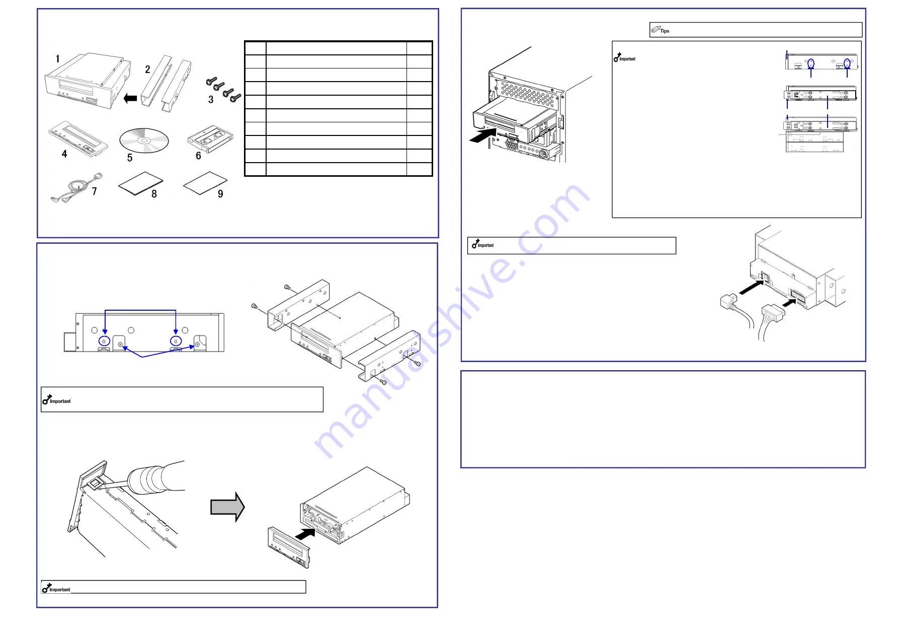
3. Mounting on the Basic Processing Unit
The procedure for installing the drive in a server is as follows.
(1) Install the Built-In DAT as shown here.
(2) Connect the 10-pin connector of INT
USB interface cable to the USB
connector on mother board.
Connect the 4-pin connector of
branched cable to the FDD
connector, and the USB connector
on the other end to the USB
connector of Built-In DAT (USB).
(3) Connect the cables to the drive as shown in the figure below.
Use the INT USB cable provided with the device.
2. Change procedure to 3.5-in device
When you want to use the Built-In DAT as a 3.5-in device, you need to remove the left and right brackets.
(1)
To Remove the Brackets
Using a Phillips screwdriver, remove the screws, and then the brackets.
(2)
Replacing the Front Bezel
1. Verify the packed contents
Make sure that you store the brackets and screws in a safe place. Only use
these screws when installing the brackets. They are metric screws (length: 4.0
mm). Using longer screws could result in damage to the device.
Insert a Phillips screwdriver into the hooks on both
sides of the front panel to release the hooks.
To install a front bezel, align the cartridge slot of the front bezel with
that of the basic processing unit, and push the front bezel straight to
the basic processing unit to engage until it clicks.
When you replaced the front panel, stick the dust-proof seal as before.
Verify the packed contents with the part list given below and ensure that all the components
and parts are present. Also, check that each item is undamaged. If a component or part is
missing or damaged, contact your dealer.
4.
<
Using the ASR function
>
When using the ASR (Automated System Recovery*) function in Windows, you must download and install the
device driver files from a floppy disk. Prepare a blank floppy disk, and copy the files in the “Tape Driver” folder
on the supplied CD to the blank floppy disk.
The Tape Driver folder itself shall not be included in the directory tree.
*ASR (Automated System Recovery)
Supported by Windows XP and Windows Server 2003, this function backs up the OS, system state, hardware
composition, and applications on your computer, allowing you to restore them in one step when recovering from
a crash. For more details on using this function, refer to the manual for your OS and backup software.
Windows 2000 and Windows server 2008 and Windows server 2012 does not support the ASR function.
DC power cable
(unused power supply
connector in the computer)
・
When using the rails with this device, use the
screw holes in the front bezel illustrated in Fig. 1
(see Fig. 2). (Perform the same operation on the
opposite side. Secure two screws on each side,
four screws total.)
In some cases the rails may extend all the way to
the front bezel molding. This causes no
problems.
When using the rails, adjust their mounting
positions so that the front bezel of this device is
aligned with the front bezels of other standard
components (such as the DVD-ROM drive).
(The shape of the rails varies according to the
model of the device.)
・
The screws needed with the 5.25-in and 3.5-in
devices are the same.
・
Always use the screws that are provided with
this device. The screws that are provided with
this device are metric screws (length: 4.0 mm).
Using screws that are longer than the screws
that are provided with this device could result in
damage to the device.
However, you may be required to use screws
coming with the basic processing unit. Refer to
the User's Guide of the basic processing unit.
INT.USB
interface cable
(4)After connecting the USB cable, bundle the cable so that it does not
interfere with the other devices or fan.
(5) Attach the cover to the basic processing unit. Plug the
power cable to the outlet.
(6) Turn on the basic processing unit.
Some servers require the rails to be used. For details on how to
install the rails, refer to the server's operating manual.
Screw holes
Rail
Fig.3
Fig.2
Front bezel
Fig.1
Front bezel
If you do not use the floppy disk drive, put the cable for
FDD connector in a vacant place in the server.
Parts name
Qty.
1
N8151-78A Built-In DAT(USB)
1
2
Brackets
※
installed
2
3
Screws
4
4
Front panel (for 3.5-inch device)
1
5
CD (Device driver ,User’s Guide)
1
6
Cleaning cartridge
1
7
INT.USB cable
1
8
Startup Guide (this manual )
1
9
Instructions on handling the DAT unit
1
INT.USB cable: Internal USB Cable
Mounting screw holes
Bracket screws


