background image

POWER

POWER

/STANDBY

SOURCE SELECT

VOLUME

ONO) R

UDIO

PROCEED

EXIT

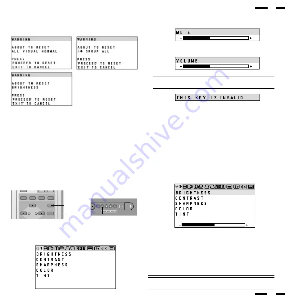
i. NORMAL( visual)

Press to reset all the stored adjustment visual data and recall the factory

preset data. When a specific control is selected, this key resets the

selected visual adjustments.

j. MUTE

Press to turn off the sound for a short period of time; press again to restore

the sound.

k. VOLUME

Press 

 to increase the sound: press 

 to decrease the sound.

NOTE: When pressing a key that does not correspond to the function currently in

use, the following message will be displayed on the monitor.

Accessing OSM

Press the PROCEED key on the remote control or front bezel.

To turn off OSM

Press the EXIT key on the remote control or front bezel.

OSM Menus

On-Screen Manager' s menu of Controls gives you an overview of the

selection of controls available.

Visual Controls Group

The visual controls allow you to adjust the picture controls such as

brightness, contrast, color, tint, and sharpness.

BRIGHTNESS

:

Pr or -  increases or decreases the image brightness level.

CONTRAST

:

Pr or -  increases or decreases the image contrast level.

SHARPNESS

:

Pr or - increases or decreases the image sharpness level.

COLOR

:

Pr or - increases or decreases the image color saturation level

TINT

:

Pr or - increases or decreases the red and green values.

NOTE: The color, tint and sharpness controls are not available for RGB input, and

the tint is not available for PAL input.

NOTE: Pressing the visual NORMAL key resets all the visual controls to the

factory settings when only the visual controls group icon is highlighted.

EXIT

PROCEED

RGB 2

RGB 1

VIDEO 2

VIDEO 1

POSITION / CONTROL

PROCEED

EXIT

25

26

Summary of Contents for MultiSync XV29 Plus

Page 1: ... NEC Technologies Inc 1250 N Arlington Heights Road Suite 500 Itasca Illinois 60143 1248 Printed in Thailand 78408751 MultiSync is a registered trademark of NEC Technologies Inc in the U S A NEC is registered trademark of NEC Corporation 1993 by NEC Technologies Inc NEC Technologies ...

Page 2: ... other than cleaning is required Use a soft cloth and if necessary mild deter gent Do not use commercial spray cleaners which may damage the surface In case of damage arrange for repairs at an authorized NEC Service Center For operating safety and to avoid damage to the unit read carefully and observe the following instructions To avoid shock and fire hazards 1 Provide adequate space for ventilati...

Page 3: ...trocution et d incendie 1 Réserver un espace libre suffisant pour la ventilation afin d éviter une accumulation de chaleur interne Ne pas couvrir les trous d aération arrière ou installer l appareil dans un coffret fermé ou sur une étagère Si l appareil est posé sur un coffret ou une étagère la température doit être maintenue en dessous de 40 C 2 Ne pas utiliser la fiche polarisée du cordon d alim...

Page 4: ...h is not distributed in the U S A Canada and Mexico by NECTECH or which is not purchased in the U S A Canada and Mexico from an authorized NECTECH dealer If you are uncertain as to whether a dealer is authorized please contact NECTECH at 800 836 0655 Any questions or problems you have with our XP29Plus XM29Plus contact NECTECH at 800 836 0655 2 Any product on which the serial number has been defac...

Page 5: ...sition 19 4 Operation Power General Controls Degaussing 21 Using OSM Controls 22 Direct Control Screen 23 Accessing OSM 26 OSM Menus 26 CONTENTS Visual Controls Group 26 H position H width Pin cushion Controls Group 27 V position V height V linearity Controls Group 27 Keystone Tilt Rotation Scan Select Controls Group 28 RGB Controls Group 29 OSM Location OSM Turn Off Time Control 29 Source Informa...

Page 6: ...ements your presentation environment and enhances the professionalism of your presentations Microsoft Plug and Play compatibility The only monitors in their class to include this standard that automatically optimizes display settings Supports most IBM VGA S VGA XGA Macintosh or any other RGB signals within a horizontal frequency range or 15 5 to 50 kHz and a vertical frequency range of 55 to 90 Hz...

Page 7: ...the OSM mode The OSM screen disappears 8 PROCEED Press to access OSM The OSM screen is displayed 9 VIDEO 2 VIDEO 2 IN RCA type Connect a VCR or laser disk player here to display the video S VIDEO 2 IN Here is where you connect S Video input from an external source like a VCR AUDIO R IN This is your right channel audio input for stereo sound coming from video 2 or RGB 2 input or audio system AUDIO ...

Page 8: ...ere you connect RGB right audio output from a computer or another RGB source AUDIO L IN MONO This is where you connect RGB left audio output from a computer or another RGB source ON 1 2 3 4 5 6 AC IN VIDEO1 DIP SW RGB 1 AUDIO1 IN R R R L L L RGB AUDIO IN MONITOR OUT MONO MONO 12 13 14 16 15 17 Terminal Board 15 MONITOR OUT R L Connect additional external speakers here to listen to audio coming fro...

Page 9: ...m a computer connected to the RGB 1 IN terminal RGB 2 Press to select an RGB video source from a computer NEC scan converter or document camera connected to the RGB 2 IN terminal 79645721 POWER ON RGB 2 RGB 1 VIDEO 2 VIDEO 1 POSITION CONTROL PROCEED EXIT SCAN NORMAL SIDE PIN HEIGHT WIDTH BRIGHT CONTRAST MUTE NORMAL VOLUME OFF DEGAUSS MULTIMEDIA MONITOR RD 346E 1 3 5 6 2 4 OSM Control 4 POSITION CO...

Page 10: ...icture Press and hold t for a darker picture 13 CONTRAST Adjusts the image brightness in relation to the background Press and hold for higher contrast Press and hold for lower contrast NOTE The VISUAL CONTROL storing operation is effective only for one input VIDEO1 VIDEO 2 RGB 1 or RGB 2 14 NORMAL This key resets the visual control settings and recalls the factory preset data NOTE The brightness a...

Page 11: ... for a long period remove the batteries Do not use new and old batteries together or use different types of batteries together Do not take apart the batteries heat them or throw them into a fire Operating Range The infrared signal operates by line of sight up to a distance of approximately 22 feet 7 m and within a 60 degree angle of the remote sensor of the monitor The monitor will not function if...

Page 12: ...h setting use a pointed object such as a pen or pencil to push the switch to the desired position Set all the pin except No 2 to the OFF OPEN position during normal operation The pins nos 5 and 6 are not used Pin No 1 Sync Control The No 1 pin sets Sync Control Set the No 1 pin to the OFF OPEN position during normal operation The monitor automatically determines if the input signal is separate syn...

Page 13: ...e supplied to D Sub Mini 15 pin input To VIDEO IN R L inputs ON 1 2 3 4 5 6 AC IN VIDEO1 DIP SW RGB 1 AUDIO1 IN R R R L L L RGB AUDIO IN MONITOR OUT MONO MONO IBM XGA SuperVGA VGA or Compatibles LINE or AUX input L R Stereo amp VCR Laser disc player or Document camera Video copy stand or Multimedia application AC Outlet 120V 220 240V Signal cable supplied to D Sub Mini 15 pin input To Video in R L...

Page 14: ...your monitor s image and monitor may require Connecting Your VCR or Laser Disc Player Using a common RCA cable and RCA audio cables not provided to connect your VCR or laser disc player to your MultiSync XV29 Plus monitor To make these connections simply 1 Turn off the power to your monitor and VCR or laser disc player 2 Connect one end of your RCA video cable to the video output connector on the ...

Page 15: ...ignments and Signal Levels for 15 pin RGB Signal to be connected D SUB 15 pin RED GREEN or Sync Green BLUE No Connection H or Composite sync V SYNC No Connection GND GND GND GND GND GND No Connection No Connection 1 2 3 4 5 11 12 13 14 15 6 7 8 9 10 D SUB 15pin RGB Input Connector 19 20 ...

Page 16: ...ng transportation a severe magnetic field can be encountered which may require demagnetizing to clear the problem Also if powered on for extended periods of time magnetic fields can be produced by the CRT itself causing color impurities In these cases use the DEGAUSS key once to demagnetize the picture tube Pressing this key once demagnetizes the picture tube for 5 seconds CAUTION Please allow a m...

Page 17: ...r control screen press any one of the other keys To end the OSM display press EXIT If no key operation is made within 3 seconds the OSM display will disappear a POSITION CONTROL Press to move the image right Press to move the image left Press to move the image up Press to move the image down b WIDTH Press to adjust the horizontal size of the image g BRIGHT Press to adjust the brightness of video d...

Page 18: ...Manager s menu of Controls gives you an overview of the selection of controls available Visual Controls Group The visual controls allow you to adjust the picture controls such as brightness contrast color tint and sharpness BRIGHTNESS Pressing or increases or decreases the image brightness level CONTRAST Pressing or increases or decreases the image contrast level SHARPNESS Pressing or increases or...

Page 19: ...ION Pressing or decreases or increases the curvature of the sides either inward or outward PIN BALANCE Pressing or increases or decreases the curvature of the sides to right or to left PIN CORNER Pressing or decreases or increases the curvature of the four corners inward outward NOTE The V LINEARITY controls allow you to adjust the spacing of the areas on the screen The object of this control is t...

Page 20: ...s after the last touch of a key to shut off the OSM menu The preset choices are 5 10 30 and 120 seconds Note that 30 seconds is the factory preset OSM H POSI Pressing or moves the OSM menu right or left OSM V POSI Pressing or moves menu up or down OSM TURN OFF TIME Pressing or selects the preset time in increasing or decreasing order Source Information Source Information provides you information a...

Page 21: ...tings The above warning statement will appear to confirm that you do want to reset individual settings NOTE In addition to OSM controls adjustments can be directly accessed with the remote control keys When adjusting with the remote control keys the on screen display for the related adjustment appears instead of the OSM menu When OSM ON OFF is set at OFF in the System Control menu OSM controls are...

Page 22: ... function as follows POSITION CONTROL up down highlights one of the control items in the System control menus POSITION CONTROL proceeds to the selected menu choice POSITION CONTROL exits the current control and returns to its original System control menus EXIT exits the OSM controls POWER ON MODE This control allows you to set the monitor to default to any one of its inputs each time the monitor i...

Page 23: ... OFF This control allows you to enable the OSM control The OSM control is available when ON is selected When the OSM does not appear the visual and raster controls are available with the remote control 35 36 ...

Page 24: ... Press again to restore sound Secure all cable connections Check volume controls of all components Install new batteries Point remote control directly at Sensor Window Use the remote control unit within 30 left and right of center at a distance of within 22ft Set Pin no 2 of DIP SW to ON OPEN Check the input signal Possible Cause Power cord unplugged Power outlet inactive Power of external equipme...

Page 25: ...n Green Video 0 3Vp p Negative Video Input Terminals 1 0Vp p 75 Ohms unbalanced RCA Jack Composite video signal Sync negative VIDEO 1 2 Y 1 0Vp p 75 Ohms unbalanced Sync negative S VIDEO Video 1 2 C 0 28Vp p 75 Ohms unbalanced Color burst level Audio Input Terminals Left Mono 0 5 Vrms high impedance Pin Jack VIDEO 1 2 RGB Right 0 5Vrms high impedance Pin Jack Monitor Output Terminal Left 0 5 0 1 V...

Page 26: ...g AC 120 V 220 240 V 50 60 Hz Power Consumption XV29 Plus XV 2940 3 3 A maximum Dimensions 25 7 W 222 8 H 219 5 D inches 625 W 2578 H 2495 D mm Weight 97 lbs 44 0 kg Environmental Considerations Operating Temperature 0 to 40 Humidity 0 to 90 Altitude 0 to 10 000 feet Storage Temperature 10 to 50 Humidity 0 to 95 Altitude 0 to 45 000 feet Regulations UL Approved UL 1950 CSA certified Meets FCC clas...

Page 27: ...Dimensions 25 7 652 19 5 495 22 5 572 6 43 44 unit inch mm 0 24 6 ...

Page 28: ... Chart Separate Sync Timing Charts VIDEO A B C D E O P Q R S VIDEO Sync Polarity Positive Negative HORIZONTAL VERTICAL Composite Sync A B C D E VIDEO O P Q R S VIDEO Sync Polarity Positive Negative HORIZONTAL VERTICAL 45 46 ...

Page 29: ...hen at 15KHz Horizontal blanking should exceed 15 75 10µsec 31KHz fH 66KHz 3 6 µsec 66KHz fH 2 7 µsec Vertical Duty should be 0 2 to 10 Vertical sync width should exceed 40 µsec or 2 horizontal lines Vertical sync width plus back porch should exceed 0 4 msec Interlaced signals are not recommended Interlaced signals with composite sync may not be displayed A B C D E VIDEO O P Q R S P VIDEO Sync Pol...

Page 30: ...ntal Pulse Width C Horizontal Back Porch D Horizontal Active Area E Horizontal Front Porch 640 480 37 860KHz 26 413µsec 1 270µsec 4 063µsec 20 317µsec 0 762µsec VESA 640 480 at 72Hz VESA 800 600 at 56Hz 800 600 35 156KHz 28 444µsec 2 000µsec 3 556µsec 22 222µsec 0 667µsec 1024 768 48 363KHz 20 677µsec 2 092µsec 2 462µsec 15 754µsec 0 369µsec VESA 1024 768 at 60Hz 1024 768 35 587KHz 28 100µsec 3 91...

Page 31: ...sec 0 051msec 0 813msec 12 190msec 0 279msec Resolution Vertical Frequency O Vertical Period P Vertical Pulse Width Q Vertical Back Porch R Vertical Active Area S Vertical Front Porch 640 480 72 809Hz 13 735msec 0 079msec 0 740msec 12 678msec 0 238msec VESA 640 480 at 72Hz VESA 800 600 at 56Hz 800 600 56 250Hz 17 778msec 0 057msec 0 626msec 17 067msec 0 028msec 1024 768 60 000Hz 16 667msec 0 124ms...

Page 32: ...4KHz MODE3 34 4 36 5KHz MODE4 36 5 41 5KHz MODE5 41 5 45 0KHz MODE6 45 0 49 0KHz MODE7 49 0 51 0KHz NEG POS NEG NEG POS NEG H H H L H L H H H L H H L F05 F06 F06 F06 F06 F06 F06 F07 F07 F07 U14 U15 U16 U17 U18 U19 U20 U21 U22 U23 REUTER 6402480 38 4KHz 72Hz VESA 6402480 43 3KHz 85Hz VESA 10242768 48 4KHz 60Hz VESA 8002600 46 9KHz 75Hz REUTER 8002600 48 1KHz 72Hz H 98 11202750 50 0KHz 60 1Hz MAC 83...

Page 33: ...f this is a reseller who is unable to provide service call NEC directly at 1 800 836 0655 DOA Policy A product is considered DOA if it fails to function according to current published specifications because of defects in NECTECH factory materials and or workmanship during the first 30 days from the date of purchase by the end user After the 30 day period any defective product will be considered a ...

Reviews: