NEC Display Solutions
Video Wall Installation Guide
2
1.
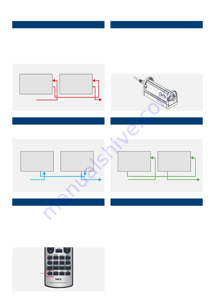
LAN cable Daisy Chain
Used for controlling monitors via network management system (e.g. NEC
NaViSet Administrator 2), external remote kit KT-RC3 and for display
calibration.
Note:
LAN1: input, LAN 2: output. Alternatively, RS232 input can be used
for the first monitor.
3.
DisplayPort Daisy Chain
Used for forwarding video signals from the following sources: DisplayPort
and OPS Slot-in PC.
5.
How to program the correct ID on the Remote Control
The Remote Control can be configured to manage a dedicated monitor or
all monitors in parallel.
•
All displays in parallel: Hold REMOTE ID SET (key bottom left) and
press button “0”
•
Dedicated display (e.g. Display 1): Hold REMOTE ID SET (key
bottom left) and press button “1”
6.
Connect an source to the primary monitor
Connect your external PC to the DisplayPort, HDMI or DVI interface on
the first monitor. Alternatively, utilise an OPS Slot-in PC or the integrated
Media Player embedded into the first monitor for a neat and seamless
solution.
In the case of using OPS-PC as a source, the internal OPS-PC interface
should be configured as “DisplayPort” to achieve the highest signal quality
(3840 x 2160, 60 Hz).
The default setting is “AUTO” for highest compatible resolution.
For manual setup of the OPS-PC interface, use the remote control on the
Primary Monitor:
•
Menu:
OPTION
>
SLOT2 CH SETTING
>
CH1
>
SET
•
Menu:
OPTION
>
SLOT2 CH SELECT
>
DisplayPort
>
SET
4.
HDMI Daisy Chain
Used for forwarding video signals from the following sources: HDMI, DVI,
internal Media Player and OPS Slot-in PC.
2.
Connect remote IR sensor (KT-RC3)
Connect the sensor to the first screen in the LAN daisy chain using the
supplied 3.5mm jack cable. (connect to interface “REMOTE” on the first
screen)
Note:
The sensor allows you to benefit from the ambient light sensor and
the human sensor, it also serves as a conventional IR receiver enabling
you to control the wall via the remote control. The KT-RC3 sensor kit,
including remote control is sold separately.
DISPLAY 1
FROMNETWORK
MANAGEMENT
TO DISPLAY 3
LAN 1
LAN 1
LAN 2
LAN 2
DISPLAY 2
EXTERNAL
SOURCE
DISPLAY 1
HDMI 1
HDMI 1
HDMI OUT
HDMI OUT
TO DISPLAY 3
DISPLAY 2
DISPLAY 1
EXTERNAL
SOURCE
TO DISPLAY 3
DP OUT
DP1
DP OUT
DP1
DISPLAY 2
REMOTE ID
SET


