background image

English-12

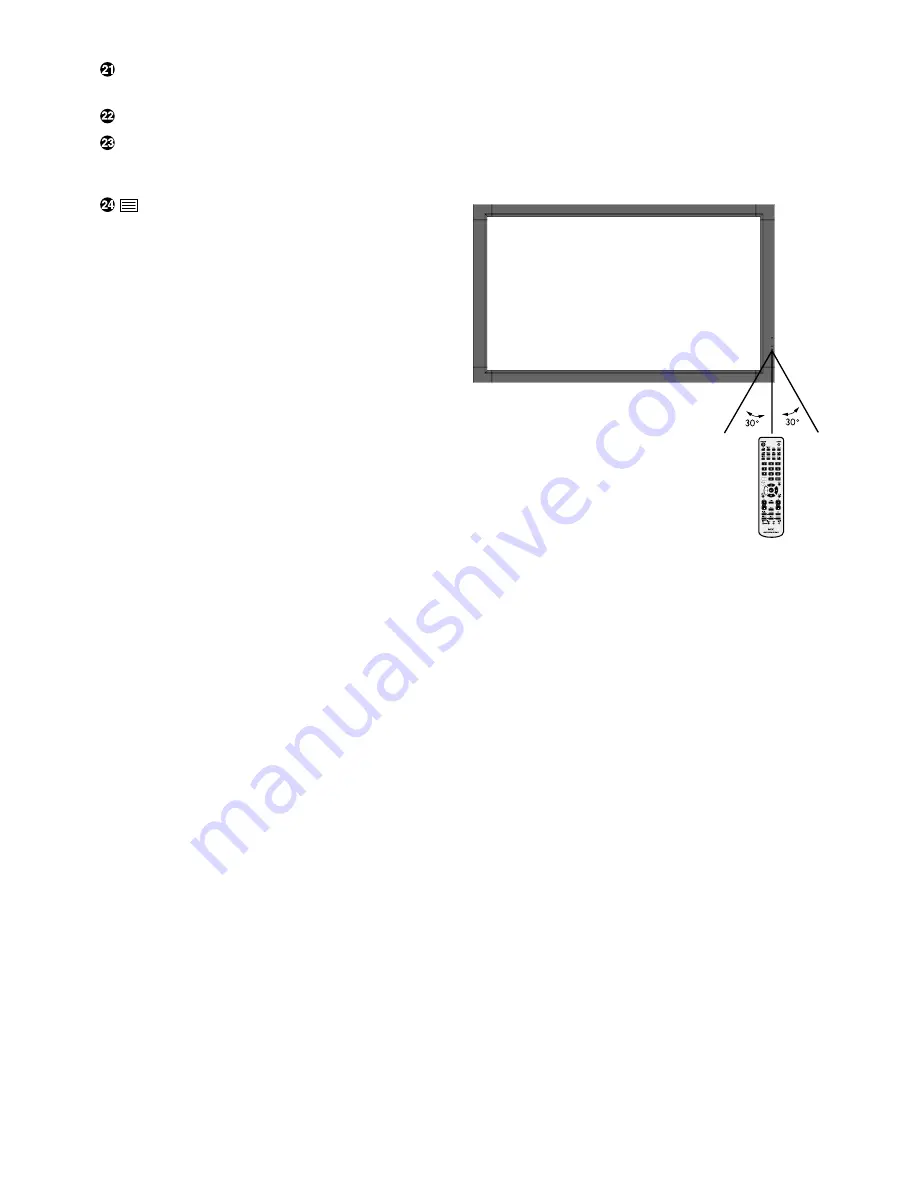
Operating Range for the Remote
Control

Point the top of the remote control toward the LCD monitor’s
remote sensor during button operation.

Use the remote control within a distance of about 7 m (23 ft.)
from remote control sensor or at a horizontal and vertical
angle of within 30° within a distance of about 3.5 m (10 ft.).

Caution:

Important, the remote control
system may not function when
direct sunlight or strong
illumination strikes the remote
control sensor or when there is an
object in the path.

Handling the remote control

Do not subject to strong shock.

Do not allow water or other liquid to splash the remote
control. If the remote control gets wet, wipe it dry
immediately.

Avoid exposure to heat and steam.

Other than to install the batteries, do not open the
remote control.

 REMOTE ID button

Activates REMOTE ID function.

 MTS button*

 AUDIO INPUT button

Selects audio input source [IN1], [IN2], [IN3], [HDMI],
[DPORT], [TV]*

1

, [OPTION]*

1

.


 button

Activates closed captioning.
Note: VIDEO1, VIDEO2, S-VIDEO inputs only.

*:

This button’s action depends on which option board you use.
Refer to the option board’s manual for further information.

*1: The product you purchased may not have this feature.

Summary of Contents for MultiSync P701

Page 1: ...User s Manual MultiSync P701 ...

Page 2: ...yPort English 16 Basic Operation English 17 Power ON and OFF Modes English 17 Power Indicator English 18 Using Power Management English 18 Selecting a video source English 18 Picture Aspect English 18 Information OSD English 19 Picture Mode English 19 OSD On Screen Display Controls English 20 PICTURE English 21 ADJUST English 21 AUDIO English 22 SCHEDULE English 22 PIP English 23 OSD English 23 MU...

Page 3: ...is own expense If necessary the user should contact the dealer or an experienced radio television technician for additional suggestions The user may find the following booklet prepared by the Federal Communications Commission helpful How to Identify and Resolve Radio TV Interference Problems This booklet is available from the U S Government Printing Office Washington D C 20402 Stock No 004 000 003...

Page 4: ...problems Declaration Declaration of the Manufacturer We hereby certify that the color monitor MultiSync P701 L709NG is in compliance with Council Directive 2006 95 EC EN 60950 1 Council Directive 2004 108 EC EN 55022 EN 61000 3 2 EN 61000 3 3 EN 55024 and marked with NEC Display Solutions Ltd 4 13 23 Shibaura Minato Ku Tokyo 108 0023 Japan CAUTION Please use the power cord provided with this displ...

Page 5: ...not connect to a peripheral device with wiring that might have excessive voltage Connecting to a TV Cable distribution system should be grounded earthed in accordance with ANSI NFPA 70 the National Electrical Code NEC in particular Section 820 93 Grounding of Outer Conductive Shield of a Coaxial Cable The screen of the coaxial cable is intended to be connected to earth in the building installation...

Page 6: ... the monitor 1 Type and number of power cords included will depend on the where the LCD monitor is to be shipped When more than one power cord is included please use a power cord that matches the AC voltage of the power outlet and has been approved by and complies with the safety standard of your particular country Power Cord 1 Setup Manual CD ROM Setup Manual Video Signal Cable Mini D SUB 15 pin ...

Page 7: ...mounted Mounting on wall or ceiling is the customer s responsibility Not all walls or ceilings are capable of supporting the weight of the unit Product warranty does not cover damage caused by improper installation remodelling or natural disasters Failure to comply with these recommendations could result in voiding the warranty DO NOT block ventilated openings with mounting accessories or other ac...

Page 8: ...ted clockwise so that the left side is moved to the top and the LED indicator light is on the bottom This will allow for proper ventilation and will extend the lifetime of the monitor Improper ventilation may shorten the lifetime of the monitor LED Indicator Mounting location The ceiling and wall must be strong enough to support the monitor and mounting accessories DO NOT install in locations wher...

Page 9: ...re that the wall can support the weight of the monitor Be sure to remove the cord or chain from the wall before moving the LCD Do not use the eyebolt M8 except in prevent tipping Allow adequate ventilation or provide air conditioning around the monitor so that heat can properly dissipate away from the unit and mounting apparatus especially when you use monitors in multiple screen 3 Ventilation Req...

Page 10: ...ontrol completely locks out access to all Control Key functions To activate the control key lock function press both and and hold down simultaneously for more than 3 seconds To resume user mode press both and and hold simultaneously for more than 3 seconds The product you purchased may not have this feature POWER button Switches the power on off See also page 17 MUTE button Switches the audio mute...

Page 11: ...AN connection See page 31 REMOTE IN OUT Use the optional wired remote control by connecting it to your monitor NOTE When you use Remote IN OUT IR CONTROL in OSD menu should be NORMAL AC IN connector Connects with the supplied power cord Main Power Switch On Off switch to turn main power ON OFF DISPLAYPORT connector To input DisplayPort signals HDMI connector To input digital HDMI signals DVI IN DV...

Page 12: ...vention EXTERNAL SPEAKER TERMINAL To output the audio signal from AUDIO 1 2 3 DPORT HDMI and TV jack Note This speaker terminal is for 15W 15W 8 ohm speaker Option board slot Slot for board accessories Please contact your supplier for detailed information ...

Page 13: ...page 21 EXIT button Returns to previous menu within OSD menu UP DOWN button Acts as button to move the highlighted area up or down to select adjustment items within OSD menu Small screen which adjusted PIP mode moves up or down MINUS PLUS button Increases or decreases the adjustment level within OSD menu settings Small screen which adjusted PIP mode moves left or right SET button Makes selection V...

Page 14: ...n object in the path Handling the remote control Do not subject to strong shock Do not allow water or other liquid to splash the remote control If the remote control gets wet wipe it dry immediately Avoid exposure to heat and steam Other than to install the batteries do not open the remote control REMOTE ID button Activates REMOTE ID function MTS button AUDIO INPUT button Selects audio input sourc...

Page 15: ...eries The remote control is powered by two 1 5V AA batteries To install or replace batteries NEC recommends the following battery use Place AA size batteries matching the and signs on each battery to the and signs of the battery compartment Do not mix battery brands Do not combine new and old batteries This can shorten battery life or cause liquid leakage of batteries Remove dead batteries immedia...

Page 16: ...d Make volume adjustments when required 9 Adjust the screen See pages 21 and 22 Make adjustments of the screen display position when necessary 10 Adjust the image See page 21 Make adjustments such as brightness or contrast when required 11 Recommended Adjustments To reduce the risk of the Image Persistence please adjust the following items based on the application being used SCREEN SAVER SIDE BORD...

Page 17: ...E VIDEO BNC MODE COMPONENT DVI MODE DVI PC BNC MODE RGB Input signal name DVD HD1 DVI HDMI SCART VIDEO1 S VIDEO VIDEO2 DVD HD2 VGA DVI RGB HV DPORT Connecting Audio terminal AUDIO IN1 IN2 IN3 AUDIO IN1 IN2 IN3 HDMI AUDIO IN1 IN2 IN3 AUDIO IN1 IN2 IN3 AUDIO IN1 IN2 IN3 AUDIO IN1 IN2 IN3 AUDIO IN1 IN2 IN3 AUDIO IN1 IN2 IN3 AUDIO IN1 IN2 IN3 AUDIO IN1 IN2 IN3 DPORT Input button in remote control DVD ...

Page 18: ...o DVI standards Connecting a DVD Player with HDMI out Please use an HDMI cable with HDMI logo It may take a moment for the signal to appear PC DVI signals are not supported Connecting a Computer with DisplayPort Please use DisplayPort cable with DisplayPort certified logo It may take a moment for the signal to appear Please note that DisplayPort connector does not supply power to the connected com...

Page 19: ...ll turn green while powered on and will turn red or amber while powered off NOTE The Main Power Switch must be in the ON position in order to power up the monitor using the remote control or the Power Button on the front of the LCD Power Button Main Power Switch ON OFF Using the remote control ...

Page 20: ...his function may not operate Selecting a video source To view a video source Use the input button to set VIDEO1 VIDEO2 S VIDEO Use the COLOR SYSTEM menu to set AUTO NTSC PAL SECAM PAL60 4 43NTSC according to your video format Aspect ratio of image NORMAL ZOOM DYNAMIC FULL WIDE 4 3 Squeeze Letterbox Unchanged view 6 Recommended selection for picture aspect 6 6 Grey areas indicate unused portions of...

Page 21: ... AMBIENT1 or AMBIENT2 BRIGHTNESS AUTO BRIGHTNESS and BRIGHTNESS in SCREEN SAVER function are disabled Do not cover Ambient light sensor when you use AMBIENT1 or AMBIENT2 in PICTURE MODE AMBIENT parameter setting PICTURE MODE in OSD select AMBIENT1 or AMBIENT2 and set IN BRIGHT and IN DARK in each mode IN BRIGHT This is the brightness level that the monitor will go up to when the ambient light leve...

Page 22: ...N button to select Press INPUT button to decide Press UP or DOWN PLUS or MINUS button to select Press EXIT Control Panel OSD screen PICTURE MODE Goto Adjustment Select Return Close 70 50 50 50 50 50 THANK YOU FOR SAVING THE ENVIRONMENT CARBON FOOTPRINT 86 0 Input source Main Menu Icons Main Menu Item Sub Menu Key Guide Adjustment Settings NOTE Some functions may not be available depending on the m...

Page 23: ...amma for use with a PC 2 4 Good for video TV DVD etc S GAMMA Special gamma for certain types of movies Raises the dark parts and lowers the light parts of the image S Curve DICOM SIM DICOM GSDF curve simulated for LCD type PROGRAMMABLE A programmable gamma curve can be loaded using NEC optional software MOVIE SETTINGS NOISE REDUCTION Adjusts the amount of noise reduction Press or to adjust 6 2 TV ...

Page 24: ...he aspect ratio while zooming 1 00 H ZOOM Amount of horizontal zoom Can be adjusted for each BASE ZOOM setting 1 00 V ZOOM Amount of vertical zoom Can be adjusted for each BASE ZOOM setting 1 00 H POS Horizontal position Can be adjusted for each BASE ZOOM setting 0 V POS Vertical position Can be adjusted for each BASE ZOOM setting 0 ASPECT Selects picture aspect FULL NORMAL WIDE and ZOOM See page ...

Page 25: ...es the size of the Text Ticker in relationship to the overall screen size BLEND Sets the transparency of the Text Ticker 0 transparent 100 opaque DETECT Enables auto detection of the Text Ticker FADE IN Enables fade in of the text ticker SUB INPUT Selects sub picture input signal Depend on signal input PIP RESET Resets PIP options back to factory settings except ASPECT and SUB INPUT LANGUAGE Selec...

Page 26: ...remote controller To return to normal operation press the DISPLAY button on the remote controller for 5 seconds TILE MATRIX Allows one image to be expanded and displayed over multiple screens up to 100 through a distribution amplifier NOTE Low resolution is not suitable for tiling to a large number of monitors You can operate without a distribution amplifier at the lower number of screens H MONITO...

Page 27: ...SPLAY PROTECTION menu back to factory setting RESET POWER SAVE STANDBY MODE FAN CONTROL SCREEN SAVER SIDE BORDER COLOR AUTO BRIGHTNESS DDC CI INPUT DETECT Selects the method of input detection the monitor uses when more than two input devices FIRST DETECT All inputs except for TV are connected NONE The Monitor will not search the other video input ports FIRST DETECT When the current video input si...

Page 28: ...ing INTERLACE Disables IP conversion This setting is best suited for motion pictures but increases the risk of image retention COLOR SYSTEM The selected Color System depends on the video format of the input signal AUTO VIDEO1 VIDEO2 S VIDEO inputs only AUTO Automatically chooses Color System setting based on input signal NTSC PAL SECAM 4 43 NTSC PAL 60 SCAN MODE Some video formats may require diff...

Page 29: ...mains visible on the screen Unlike CRT monitors LCD monitors image persistence is not permanent but constant images being displayed for a long period of time should be avoided To alleviate image persistence turn off the monitor for as long as the previous image was displayed For example if an image was on the monitor for one hour and a residual image remains the monitor should be turned off for on...

Page 30: ...ile using the keypad to input the REMOTE CONTROL ID number 1 100 The REMOTE ID NUMBER should match the MONITOR ID number of the display to be controlled Choose 0 to simultaneously control all displays in range 3 Point the remote control towards the remote sensor of the desired monitor and press the REMOTE ID SET button The MONITOR ID number is shown in red on the display If the REMOTE CONTROLID is...

Page 31: ...o control the SECONDARY monitor while aiming at the PRIMARY monitor The MENU OSD will appear on the selected target monitor NOTE If the ID No mode select OSD is showing press the DISPLAY button on the remote control while pointing at the PRIMARY monitor to clear this OSD HINT If you lost control due to the incorrect setting of IR CONTROL pressing the DISPLAY button on the remote control for 5 or m...

Page 32: ...ol monitor or multiple monitors that are daisy chained together please use the control command Instructions for the control command can be found on the CD included with the display The file is called External_control pdf Multiple monitors that are daisy chained have a limit to the conectable monitor 1 Interface This LCD monitor uses RXD TXD and GND lines for RS 232C control The reverse type cable ...

Page 33: ...ersion for the web browser This device uses JavaScript and Cookies and the browser should be set to accept these functions The setting method will vary depending on the version of browser Please refer to the help files and the other information provided in your software Access is gained to the HTTP server function by starting the Web browser on the computer via the network connected to the monitor...

Page 34: ...p pd nec co jp index html for the address or the entry column of the URL Example 2 When the IP address of the monitor is 192 168 73 1 access is gained to the mail alert settings by specifying http 192 168 73 1 index html for the address or the entry column of the URL Network Settings http the Monitor s IP address index html Enabling this option automatically assigns an IP address to the monitor fr...

Page 35: ...used Click this button to reflect the above settings Click this button to send a test mail to check if your settings are correct A reply to a test mail will be displayed HOST NAME DOMAIN NAME ALERT MAIL SENDER S ADDRESS SMTP SERVER NAME RECIPIENT S ADDRESS 1 to 3 APPLY EXECUTE STATUS This option notifies your computer of an error message via e mail when using wired LAN An error message notificatio...

Page 36: ...ly optimizing display performance IPM Intelligent Power Manager System Provides innovative power saving methods that allow the monitor to shift to a lower power consumption level when on but not in use saving two thirds of your monitor energy costs reducing emissions and lowering the air conditioning costs of the workplace FullScan Capability Allows you to use the entire screen area in most resolu...

Page 37: ...hould be connected Make certain the computer is not in a power saving mode touch the keyboard or mouse Check to see that the power indicator option in the OSD is set to ON RED LED on monitor is blinking A certain failure might have occurred please contact your nearest authorized NEC DISPLAY SOLUTIONS service facility If the monitor is powered off by the inside temperature being higher than the nor...

Page 38: ... S VIDEO Mini DIN 4 pin S VIDEO Y 1 0 Vp p 75 ohm C 0 286 Vp p 75 ohm NTSC 0 3 Vp p 75 ohm PAL SECAM NTSC PAL SECAM 4 43NTSC PAL60 Output Signal RGB HV BNC R G B H V Analog RGB 0 7 Vp p with 75 ohm terminated Separate HV sync TTL level Posi Nega DVD HD2 BNC Component Y 1 0 Vp p 75ohm Cb Cr Pb Pr 0 7 Vp p 75 ohm VIDEO1 VIDEO2 BNC Composite 1 0 Vp p with 75 ohm terminated AUDIO AUDIO RCA L R X2 Anal...

Page 39: ...in No Name 1 connected to 7 8 2 RXD 3 TXD 4 connected to 6 5 GND 6 connected to 4 7 connected to 1 8 8 connected to 1 7 9 NC 1 6 5 9 D SUB 9P This LCD monitor uses RXD TXD and GND lines for RS 232C control 2 REMOTE IN Pin Assignment 3 REMOTE OUT ...

Page 40: ...n or http www necdisplay com in USA Energy Saving This monitor features an advanced energy saving capability When a VESA Display Power Management Signalling DPMS Standard signal is sent to the monitor the Energy Saving mode is activated The monitor enters a single Energy Saving mode Manufacturer s Recycling and Energy Information WEEE Mark European Directive 2002 96 EC Within the European Union EU...

Reviews: