English-5
English
This device cannot be used or installed without the Tabletop
Stand or other mounting accessory for support. For proper
installation it is strongly recommended to use a trained,
NEC authorized service person. Failure to follow NEC
standard mounting procedures could result in damage to the
equipment or injury to the user or installer. Product warranty
does not cover damage caused by improper installation.
Failure to follow these recommendations could result in
voiding the warranty.
Mounting
DO NOT mount the monitor yourself. Please ask dealer.
For proper installation it is strongly recommended to use
a trained, qualifi ed technician. Please inspect the location
where the unit is to be mounted. Mounting on wall or ceiling
is the customer’s responsibility. Not all walls or ceilings are
capable of supporting the weight of the unit. Product warranty
does not cover damage caused by improper installation,
remodelling, or natural disasters. Failure to comply with these
recommendations could result in voiding the warranty.
DO NOT block ventilated openings with mounting
accessories or other accessories.
For NEC Qualifi ed Personnel:
To ensure safe installation, use two or more brackets to
mount the unit. Mount the unit to at least two points on the
installation location.
Please note the following when mounting
on wall or ceiling
•
When using mounting accessories other than those that
are NEC approved, they must comply with the VESA-
compatible (FDMlv1) mounting method.
•
NEC strongly recommends
using size M6 screws
(11-12 mm + thickness
of bracket and washer in
length). If using screws
longer than 11-12 mm,
check the depth of the hole.
(Recommended Fasten
Force: 470 - 635N•cm)
NEC recommends mounting
interfaces that comply with
UL1678 standard in North
America.
•
Prior to mounting, inspect the installation location to
insure that it is strong enough to support the weight of the
unit so that the unit will be safe from harm.
•
Refer to the instructions included with the mounting
equipment for detailed information.
•
Make sure there is no gap between the monitor and the
bracket.
Installation
Mounting
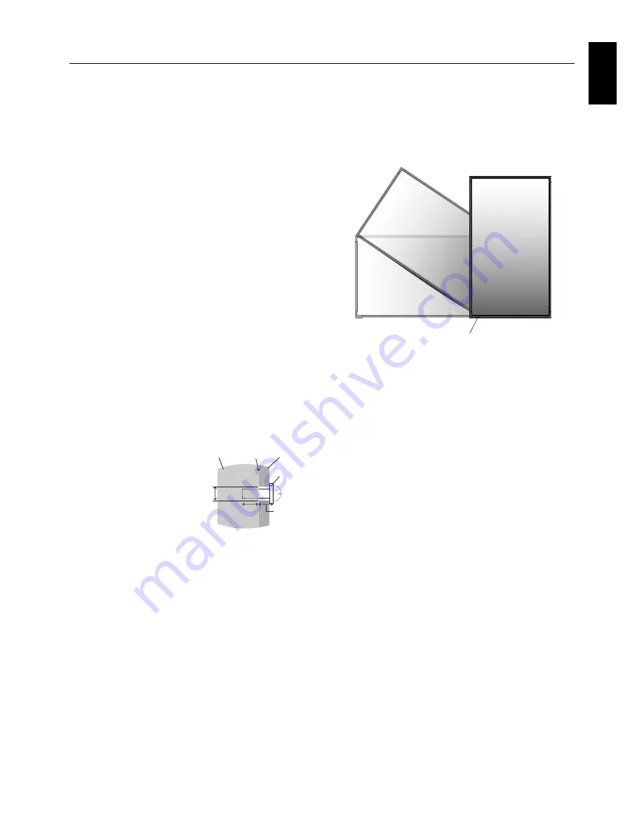
Bracket
Screw
Washer
Unit
11-12 mm
Thickness
of bracket
and washer
Screw length should equal
depth of hole (11-12 mm) + the
thickness of mounting bracket
and washer. Bracket hole
should be under
φ
8.5 mm.
under
φ
8.5 mm
No gap
Orientation
•
When using the monitor in the portrait position, the
monitor should be rotated clockwise so that the left side
is moved to the top and the LED indicator light is on
the bottom. This will allow for proper ventilation and will
extend the lifetime of the monitor. Improper ventilation
may shorten the lifetime of the monitor.
LED Indicator
Mounting location
•
The ceiling and wall must be strong enough to support the
monitor and mounting accessories.
•
DO NOT install in locations where a door or gate can hit
the unit.
•
DO NOT install in areas where the unit will be subjected
to strong vibrations and dust.
•
DO NOT install near where the main power supply enters
the building.
•
Do not install in where people can easily grab and hang
onto the unit or the mounting apparatus.
•
When mounting in a recessed area, as in a wall, leave at
least 4 inches (100 mm) of space between the monitor
and the wall for proper ventilation.
•
Allow adequate ventilation or provide air conditioning
around the monitor, so that heat can properly dissipate
away from the unit and mounting apparatus.
Mounting on ceiling
•
Ensure that the ceiling is sturdy enough to support the
weight of the unit and the mounting apparatus over time,
against earthquakes, unexpected vibrations, and other
external forces.
•
Be sure the unit is mounted to a solid structure within
the ceiling, such as a support beam. Secure the monitor
using bolts, spring lock washers, washer and nut.
•
DO NOT mount to areas that have no supporting internal
structure. DO NOT use wood screws or anchor screws for
mounting. DO NOT mount the unit to trim or to hanging
fi xtures.
Maintenance
•
Periodically check for loose screws, gaps, distortions,
or other problems that may occur with the mounting
apparatus. If a problem is detected, please refer to
qualifi ed personnel for service.
•
Regularly check the mounting location for signs of
damage or weakness that may occur over time.