background image

English

English-11

ECO MODE

Decreases the amount of power consumed by reducing the brightness level.

OFF:

 Set brightness variable range from 0% to 100%.

1:

 Set brightness variable range from 0% to 75%.

2:

 Set brightness variable range from 0% to 50%.

CUSTOM:

 Decreases the brightness level as determined by the user.

Refer to the Advanced OSD menu for custom setting instructions.

AUTO BRIGHTNESS

OFF:

 No function.

ON:

 Adjusts the brightness automatically, by detecting the brightness level of your environment and adjusting the

monitor with the best BRIGHTNESS setting*

1

.

NOTE:

Do not cover environmental brightness sensor (Ambibright sensor).

*

1

: Please refer to Page 20 for full “Auto Brightness” information.

BLACK LEVEL

Adjust the black level.

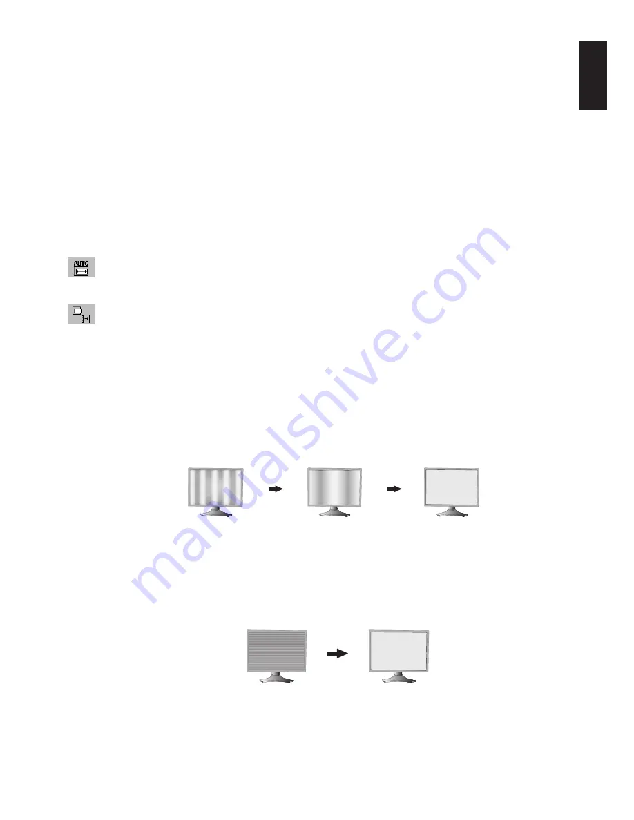
Auto Adjust (Analog input only)

Automatically adjusts the Image Position and H. Size settings and Fine settings.

Image Controls

LEFT / RIGHT (Analog input only)

Controls Horizontal Image Position within the display area of the LCD.

DOWN / UP (Analog input only)

Controls Vertical Image Position within the display area of the LCD.

H.SIZE (V.SIZE) (Analog input only)

Adjusts the horizontal size by increasing or decreasing this setting.

If the “AUTO Adjust function” do not give you a satisfactory picture setting, a further tuning can be performed using
the “H.Size (or V.Size)” function (dot clock). For this a Moiré test pattern could be used. This function may alter the
width of the picture. Use Left/Right Menu to center the image on the screen. If the H.Size (or V.Size) is wrongly
calibrated, the result would look like on the left drawing. The image should be homogeneous.

FINE (Analog input only)

Improves focus, clarity and image stability by increasing or decreasing this setting.

If the “Auto Adjust function” and the “H.Size” function do not give you a satisfactory picture setting, a fine tuning can
be performed using the “Fine” function.

For this a Moiré test pattern could be used. If the Fine value is wrongly calibrated, the result would look like on the
left drawing. The image should be homogeneous.

INPUT RESOLUTION (Analog Input Only)

Selects resolution’s priority of input signal to one of the following pair: 1360 x 768, 1680 x 1050 or 1280 x 768,
1680 x 1050 or 1024 x 768, 1400 x 1050.

1360 x 768, 1680 x 1050:

 Determines the resolution to 1360 x 768, 1680 x 1050.

1280 x 768, 1680 x 1050:

 Determines the resolution to 1280 x 768, 1680 x 1050.

1024 x 768, 1400 x 1050:

 Determines the resolution to 1024 x 768, 1400 x 1050.

When H.SIZE value is

wrong.

When H.SIZE value is

improved.

When H.SIZE value is

correct.

When FINE value is wrong.

When FINE value is correct.

Summary of Contents for MultiSync P221W

Page 1: ...MultiSync P221W User s Manual...

Page 2: ...glish 3 Contents English 5 Quick Start English 6 Controls English 10 Specifications English 14 Features English 15 Troubleshooting English 16 Appendix English 17 Using the Auto Brightness function Eng...

Page 3: ...COMPONENTS INSIDE REFER SERVICING TO QUALIFIED SERVICE PERSONNEL Declaration of the Manufacturer We hereby certify that the colour monitor MultiSync P221W L227HT is in compliance with Council Directiv...

Page 4: ...receiver is connected Consult your dealer or an experienced radio TV technician for help If necessary the user should contact the dealer or an experienced radio television technician for additional su...

Page 5: ...Immediately unplug your monitor from the wall outlet and refer servicing to qualified service personnel under the following conditions When the power supply cord or plug is damaged If liquid has been...

Page 6: ...image persistence after image effects Get regular eye checkups Ergonomics To realize the maximum ergonomics benefits we recommend the following Adjust the Brightness until the background raster disapp...

Page 7: ...Manual CD ROM Cable Cover Screw 4 M4 x 14 to mount the monitor to a flexible arm page 9 Power Cord User s Manual DVI D to DVI D cable Cable Cover CD ROM 15 pin mini D SUB male to 15 pin mini D SUB ma...

Page 8: ...to the highest position Figure C 1 4 Connect all cables to the appropriate connectors Figure C 1 NOTE Incorrect cable connections may result in irregular operation damage display quality components of...

Page 9: ...nlet must be turned on Turn on the monitor with the front power button Figure E 1 and the computer NOTE The Vacation Switch is a true on off switch If this switch is on the OFF position the monitor ca...

Page 10: ...raise the screen place hands on each side of the monitor and lift up to the highest position Figure RL 1 To rotate screen place hands on each side of the monitor screen and turn clockwise from Landsca...

Page 11: ...and removal to attach the flexible arm to the monitor Figure F 1 Caution When mounting use ONLY the screws 4 pcs that were removed from the stand to avoid damage to the monitor or stand The monitor sh...

Page 12: ...ake adjustments to various settings resulting in a more comfortable viewing experience Do not cover this sensor Turns the monitor on and off Indicates that the power is on Can be changed between blue...

Page 13: ...not give you a satisfactory picture setting a further tuning can be performed using the H Size or V Size function dot clock For this a Moir test pattern could be used This function may alter the widt...

Page 14: ...on the PC and Video card used or when another Video signal cable is attached this function may not operate VIDEO DETECT Selects the method of video detection when more than one computer is connected F...

Page 15: ...with no control To activate the OSD Lock Out function press SELECT then Right button and hold down simultaneously To deactivate the OSD Lock Out press SELECT then Right button and hold down simultane...

Page 16: ...cites 1440 x 1050 1 at 60 Hz to 75 Hz recommended resolution at 60 Hz for 1680 x 1050 at 60 Hz optimal display performance Active Landscape Horiz 474 mm 18 7 inches Display Area Vert 296 mm 11 7 inch...

Page 17: ...tilt base for preferred angle of vision small footprint and compliance with MPRII and TCO guidelines for lower emissions Plug and Play The Microsoft solution with the Windows operating system facilit...

Page 18: ...itor when not in use Message OUT OF RANGE is displayed screen is either blank or shows rough images only Image is displayed only roughly pixels are missing and OSD warning OUT OF RANGE is displayed Ei...

Page 19: ...tness level of your environment and adjusting the monitor with your BRIGHTNESS setting NOTE Do not cover environmental brightness sensor Ambibright sensor Black Level Allows you to manually adjust the...

Page 20: ...ter is connected Press Left or Right to select FIRST The video input has to be switched to FIRST mode When current video input signal is not present then the monitor searches for a video signal from t...

Page 21: ...nd CONTRAST can be adjusted while in the lock out mode OSD LOCK OUT with no control To activate the OSD Lock Out function press SELECT then Right button and hold down simultaneously To deactivate the...

Page 22: ...Figure 2 2 Set the DARK level This is the level of brightness that the monitor will go down to when the ambient light level is low Make sure the room is at its darkest when setting this level Then us...

Page 23: ...rgy Energy saving mode after a certain time beneficial both for the user and the environment Electrical safety Emissions Electromagnetic fields Noise emissions Ecology The product must be prepared for...

Page 24: ...www nec display com in Japan or http www necdisplay com in USA Energy Saving This monitor features an advanced energy saving capability When a VESA Display Power Management Signalling DPMS Standard si...

Reviews: