NEC MultiSync MA431, User Manual
The NEC MultiSync MA431 is a cutting-edge display designed for professionals seeking exceptional visual quality. To fully harness its capabilities, it is vital to have a comprehensive User Manual. Accessible for free download at manualshive.com, this manual provides in-depth instructions and insights to optimize your MA431 experience.
Share
Download


Reviews:
No comments
Related manuals for MultiSync MA431
1029
Brand: Xenarc Pages: 16
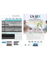
UA-851
Brand: A&D Pages: 2

UA-621
Brand: A&D Pages: 2
Viiiiva
Brand: 4iiii Pages: 2

SyncMaster TC190
Brand: Samsung Pages: 19

LCD-AP-F15
Brand: Crystal Image Technologies Pages: 32

E-MOTIVE ATOM ATOM01-000-0-40-900
Brand: AVIRE Pages: 14

DLP32B1
Brand: Daewoo Pages: 27

DRIVE MONITOR
Brand: ACRONIS Pages: 25

OZZIEMASTER 922
Brand: Akron Pages: 42

ViewPanel VP150
Brand: ViewSonic Pages: 18

Q32V4
Brand: AOC Pages: 29

BMG 4922
Brand: AEG Pages: 75

BMG 5612
Brand: AEG Pages: 166

BMG 4907
Brand: AEG Pages: 110

BMG 5610
Brand: AEG Pages: 246

BMG 5611
Brand: AEG Pages: 170
BMG 4906
Brand: AEG Pages: 166


