background image

English-22

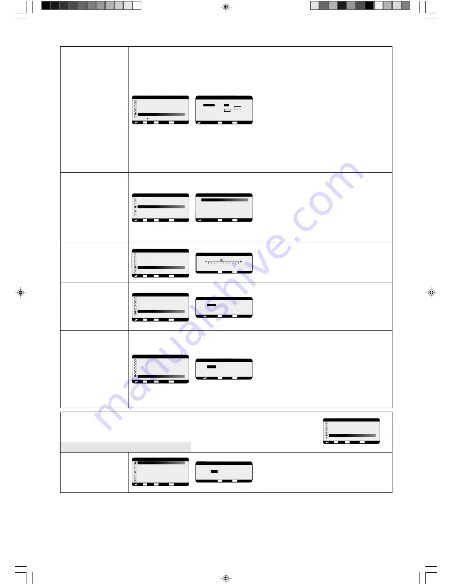
Select “SCREEN SAVER” functions to reduce the risk of
the “image persistence”.
GAMMA: The display gamma is changed and fixed when
selected “ON”.
COOLING FAN: The built in cooling fan is always on
when set “ON”.
BRIGHTNESS: The brightness is decreased when
selected “ON”.
MOTION: Image is slightly expanded and moves
4 directions (UP, DOWN, RIGHT, LEFT) periodically
(Need setting the time for movement).
Movement area is approxi/- 10mm from original
position; Please locate the important information such as
text within 90% area of screen image.
See note (1) for this functions.
PIP, POP, Side by Side and STILL will be disabled when
“MOTION” is active.

Selecting the Colour System depends on your input
video format.
AUTO: NTSC, PAL, SECAM, PAL60 or 4.43 NTSC is
automatically selected.
NTSC: Specific selection of NTSC.
PAL: Specific selection of PAL.
SECAM: Specific selection of SECAM.
PAL-60: Specific selection of PAL60.
4.43NTSC: Specific selection of 4.43 NTSC.

Adjustment the side black bar color white when 4:3
image displayed, black to white.
Press + button, the bar will become whiter.
Press - button, the bar will become darker.

Selecting the CONFIGURATION RESET allows you to
reset all configuration settings.
Select “Yes” and press “SET” button to restore the factory
preset data.
Press “EXIT” button to cancel and return the previous
menu.

Selecting “YES” allows you to reset PICTURE, SCREEN,
AUDIO, CONFIGURATION1,2 and ADVANCED OPTION
will be back to factory settings (except H POSITION,
V POSITION, CLOCK, CLOCK PHASE,
H RESOLUTION, V RESOLUTION, LANGUAGE,
DATE & TIME and SCHEDULE).
Select “YES” and press “SET” button to restore the
factory preset data.
Press “EXIT” button to cancel and return the previous
menu.

SCREEN SAVER

COLOR SYSTEM

*:INPUT VIDEO only

SIDE BORDER

COLOR

CONFIGURATION

RESET

FACTORY RESET

CONFIGURATION 1

POWER SAVE
LANGUAGE
SCREEN SAVER
COLOR SYSTEM
SIDE BORDER COLOR
CONFIGURATION RESET

FACTORY RESET

:SEL

SET

:NEXT

:RETURN

MENU

:EXIT MENU

EXIT

FACTORY RESET

:RETURN

MENU

:EXIT MENU

NO

YES

:SEL

EXIT

CONFIGURATION 1

POWER SAVE
LANGUAGE
SCREEN SAVER
COLOR SYSTEM
SIDE BORDER COLOR

CONFIGURATION RESET

FACTORY RESET

:SEL

SET

:NEXT

:RETURN

MENU

:EXIT MENU

EXIT

CONFIGURATION RESET

:RETURN

MENU

:EXIT MENU

NO

YES

:SEL

EXIT

CONFIGURATION 1

AUTO SETUP
AUTO ADJUST
AUTO BRIGHTNESS
POWER SAVE
LANGUAGE

SCREEN SAVER

SIDE BORDER COLOR

:SEL

SET

:NEXT

:RETURN

MENU

:EXIT MENU

EXIT

+ -:ADJ

:RETURN

MENU

:EXIT MENU

SCREEN SAVER

:SEL


GAMMA

  COOLING FAN
  BRIGHTNESS
  MOTION

ON

    /    OFF

ON    /    AUTO
ON    /    OFF
      10  SEC.

EXIT

CONFIGURATION 1

POWER SAVE
LANGUAGE
SCREEN SAVER

COLOR SYSTEM

SIDE BORDER COLOR
CONFIGURATION RESET
FACTORY RESET

:SEL

SET

:NEXT

:RETURN

MENU

:EXIT MENU

EXIT

COLOR SYSTEM

AUTO

DEUTSCH

NTSC
PAL
SECAM
4.43 NTSC
PAL-60

:SEL

:RETURN

MENU

:EXIT MENU

EXIT

CONFIGURATION 1

AUTO BRIGHTNESS
POWER SAVE
LANGUAGE
POWER SAVE
COLOR SYSTEM

SIDE BORDER COLOR

CONFIGURATION RESET
FACTORY RESET

:SEL

SET

:NEXT

:RETURN

MENU

:EXIT MENU

EXIT

+ -:ADJ

:RETURN

MENU

:EXIT MENU

50

SIDE BORDER COLOR

EXIT

Main-Menu

CONFIGURATION 2

Sub-Menu

A set up ON/OFF of long cable alteration can be
performed. In ON, enforcement of an AUTO Set Up
performed alteration.

Please refer to the CD-ROM included for alteration.

LONG CABLE

ON/OFF

*:INPUT RGB2/3 only

MAIN MENU

PICTURE
SCREEN
AUDIO
PIP
CONFIGURATION 1

CONFIGURATION 2

ADVANCED OPTION

:SEL

SET

:NEXT

:RETURN

MENU

:EXIT MENU

EXIT

+ -:SEL

:RETURN

MENU

:EXIT MENU

LONG CABLE ON/OFF

ON           

/             OFF

EXIT

CONFIGURATION 2

LONG CABLE ON/OFF

LONG CABLE MANUAL
OSM TURN  OFF
INFORMATION OSM
OFF TIMER
OSM POSITION
INPUT DETECT
MONITOR INFORMATION

:SEL

SET

:NEXT

:RETURN

MENU

:EXIT MENU

EXIT

01_English

10/8/06, 11:13

22

Summary of Contents for MultiSync LCD5710

Page 1: ...dr cznik u ytkownika Руководство пользователя Kullan c Klavuzu MultiSync LCD5710 57 LCD Colour Monitor This monitor is designed to operate in landscape orientation only Do not use in portrait orientation Using the monitor in portrait position can cause damage to the display and will void the warranty of the product 00_Cover_all 10 8 06 11 12 1 ...

Page 2: ...o ensure FCC compliance 2 Please use the supplied shielded video signal cable 15 pin mini D SUB to 15 pin mini D SUB 3 Please attach the ferrite cores on the Audio Cable Please see page 11 of this manual 2 This equipment has been tested and found to comply with the limits for a Class B digital device pursuant to part 15 of the FCC Rules These limits are designed to provide reasonable protection ag...

Page 3: ...English âesky Deutsch Ελληνικά Español Français Italiano Nederlands Polski Русский Türkçe 01b_XChapterOpener 10 8 06 11 12 1 ...

Page 4: ...01b_XChapterOpener 10 8 06 11 12 2 ...

Page 5: ...nnect the LCD Monitor to Macintosh English 13 Connecting with Digital Interface Equipment English 14 Connect the LCD Monitor to a Computer with a Digital Output English 14 Connecting a DVD Player with component out English 15 Connect the LCD Monitor to a DVD Player English 15 Connecting to a Stereo Amplifier English 16 Connect the LCD Monitor to a Stereo Amplifier English 16 Basic Operation Englis...

Page 6: ... voltage within the unit may have sufficient magnitude to cause electric shock Therefore it is dangerous to make any kind of contact with any part inside this unit This symbol alerts the user that important literature concerning the operation and maintenance of this unit has been included Therefore it should be read carefully in order to avoid any problems Disposing of your old NEC product Within ...

Page 7: ... ventilation around the monitor so that heat can properly dissipate Do not block ventilated openings or place the monitor near a radiator or other heat sources Do not put anything on top of the monitor The power cable connector is the primary means of detaching the system from the power supply The monitor should be installed close to a power outlet which is easily accessible Handle with care when ...

Page 8: ...ed for optional Loudspeakers Stand for the Independence x 2 Thumbscrew for stand x 2 Main switch cover CD ROM Ferrite Core x 2 Band x 2 Thumbscrew for stand x 2 Stand for the Independence x 2 Screw M4 x 8 x 4 Install the stands at the time of unpacking if the display will be used with the stand Remember to save your original box and packing material to transport or ship the monitor The following c...

Page 9: ...all Control Key functions To activate the control key lock function press both of and and hold down simultaneously for more than 3 seconds To resume back to user mode press both of and and hold simultaneously for more than 3 seconds 1 POWER button Switches the power on off See also page 16 2 MUTE button Switches the audio mute ON OFF 3 INPUT button Acts as SET button within OSM menu Toggle switche...

Page 10: ...e a computer Out connector To connect multiple MultiSync LCD5710 11 EXTERNAL SPEAKER TERMINAL To output the audio signal from AUDIO 1 2 or 3 jack 1 AC IN connector Connects with the supplied power cord 2 RGB 1 IN DVI D To input digital RGB signals from a computer or HDTV device having a digital RGB output This connector does not support analog input 3 RGB 2 IN mini D Sub 15 pin To input analog RGB...

Page 11: ...or 1080i 11 DISPLAY button To switch the information OSM on off See page 17 12 AUTO SETUP button To enter the auto setup menu See page 21 13 MENU button To switch the menu mode on off 14 UP button Acts as button to move the highlighted area up to select the adjustment with OSM menu Small screen which adjusted PIP mode moves up 15 DOWN button Acts as button to move the highlighted area down to sele...

Page 12: ...he and indications inside the case 3 Replace the cover CAUTION Incorrect use of batteries can result in leaks or bursting Be careful especially about the following points Place AA size batteries matching the and signs on each battery to the and signs of the battery compartment Don t mix battery types Don t combine new batteries with used ones It causes shorter battery life or leakage of batteries ...

Page 13: ...Remove thumbscrews with a screwdriver or with your fingers and place them in a safe place for reuse CAUTION Handle with care when mounting the display stand and avoid pinching your fingers NOTE Place stand onto monitor so that the long end of the feet are in the front 12 When using external speakers We recommend to using the option speakers designed for the MultiSync LCD5710 The external speaker t...

Page 14: ...on How to Mount and Attach Options to the LCD Monitor 2 Lay the screen face down Lay the protective sheet on a table which was wrapped around the monitor when it was packaged beneath the screen surface so as not to scratch the screen face This device cannot be used or installed without the Tabletop Stand or other mounting accessory Failure to follow correct mounting procedures could result in dama...

Page 15: ... PC Audio cable 2 Close the ferrite core Attach the two Ferrite Cores to the both ends of PC Audio Cable For PC Audio Cable Ferrite Core Connections Before making connections First turn off the power of all the attached equipment and make connections Refer to the user manual included with each separate piece of equipment Wiring Diagram LCD monitor Personal computer VCR Personal computer DVD player...

Page 16: ...LCD monitor use a signal cable which is available separately mini D sub 15 pin to BNC x 5 Select RGB 3 from the INPUT button When connecting one or more LCD monitors use the RGB OUT connector BNC The AUDIO IN 1 2 and 3 can be used for audio input For connection select AUDIO 1 2 or 3 from the AUDIO INPUT button LCD monitor LCD monitor second monitor BNC x 5 BNC x 5 PC or IBM compatible BNC x 5 Mini...

Page 17: ... cable available separately mini D sub 15 pin to BNC x 5 If you use with a Macintosh PowerBook set Mirroring to Off Refer to your Macintosh s owner s manual for more information about your computer s video output requirements and any special identification or configuring your monitor s image and monitor may require The AUDIO IN 1 2 and 3 can be used for audio input For connection select AUDIO 1 2 ...

Page 18: ...l Interface standard Connect the LCD Monitor to a Computer with a Digital Output The RGB 1 IN connector also accepts a DVI D cable Input TMDS signals conforming to DVI standards To maintain display quality use a cable with a quality prescribed by DVI standards The AUDIO IN 1 2 and 3 can be used for audio input For connection select AUDIO 1 2 or 3 from the AUDIO INPUT button Mode selection see DVI ...

Page 19: ... jack to the BNC connector cable not provided Some DVD players may have different connectors such as DVI D connector Select DVI HD mode from the DVI MODE menu when you connect a DVI D connector Mode selection see DVI MODE of page 23 The AUDIO IN 2 and 3 both RCA can be used for audio input For connection select AUDIO 2 or AUDIO 3 from the AUDIO INPUT button Connecting a DVD Player with component o...

Page 20: ...nd OFF Modes The LCD monitor power indicator will turn green while powered on or red when in off mode The monitor can be powered on or off using the following three options 1 Pressing the power button Note Before pressing the power button be sure to turn on the Main Power Switch on the LCD monitor Main Power Switch Power Button 2 Using the remote control Note Before operating the remote control be...

Page 21: ...hooting on page 28 RGB1 2 3 DVD HD VIDEO PIP or POP Main RGB2 Sub VIDEO S Information OSM Video Input mode Input signal Information Audio input mode Picture Size mode RGB2 1024 x 768 48kHz 60Hz AUDIO 1 SIZE FULL Video Input mode Audio input mode Picture Size mode DVD HD AUDIO 3 SIZE WIDE Video Input mode Input Signal Colour System mode Audio input mode Picture Size mode VIDEO S NTSC AUDIO 3 SIZE N...

Page 22: ... adjustable to get a distinct image or a soft one as you prefer and set independently for each picture mode Press button to increase sharpness Press button to decrease sharpness Adjusts the image brightness in relation to the background Press button to increase black level Press button to decrease black level NOTE sRGB picture mode is standard and cannot be changed Adjusts the noise reduction leve...

Page 23: ...MENU EXIT MENU 32 COLOR EXIT PICTURE BRIGHTNESS CONTRAST SHARPNESS TINT COLOR BLACK LEVEL NOISE REDUCTION SEL SET NEXT RETURN MENU EXIT MENU EXIT ADJ RETURN MENU EXIT MENU 32 TINT EXIT Main Menu SCREEN Sub Menu Controls Horizontal Image position within the display area of the LCD Press button to move screen to right Press button to move screen to left Controls Vertical Image position within the di...

Page 24: ...OM H POS V POS EXIT ZOOM MODE CUSTOMV 16 9 14 9 DYNAMIC OFF SEL SET NEXT RETURN MENU EXIT MENU EXIT SCREEN H POSITION V POSITION CLOCK CLOCK PHASE H RESOLUTION V RESOLUTION ZOOM MODE SCREEN RESET SEL SET NEXT RETURN MENU EXIT MENU EXIT SCREEN H POSITION V POSITION CLOCK CLOCK PHASE H RESOLUTION V RESOLUTION ZOOM MODE SCREEN RESET SEL SET NEXT RETURN MENU EXIT MENU EXIT ADJ RETURN MENU EXIT MENU 76...

Page 25: ...g the auto brightness ON OFF When select ON the brightness will be automatically adjusted Selecting RGB ON the monitor will go to power management mode when RGB1 2 3 sync is lost Selecting VIDEO ON the monitor will go to power management mode after about 10 minutes delay from when DVD HD and VIDEO input signal is lost NOTE When connecting RGB1 video card might not stop sending digital data even if...

Page 26: ...SCREEN SAVER COLOR SYSTEM INPUT VIDEO only SIDE BORDER COLOR CONFIGURATION RESET FACTORY RESET CONFIGURATION 1 POWER SAVE LANGUAGE SCREEN SAVER COLOR SYSTEM SIDE BORDER COLOR CONFIGURATION RESET FACTORY RESET SEL SET NEXT RETURN MENU EXIT MENU EXIT FACTORY RESET RETURN MENU EXIT MENU NO YES SEL EXIT CONFIGURATION 1 POWER SAVE LANGUAGE SCREEN SAVER COLOR SYSTEM SIDE BORDER COLOR CONFIGURATION RESET...

Page 27: ...en Press button to move right side of the screen Press button to move left side of the screen CONFIGURATION 2 LONG CABLE ON OFF LONG CABLE MANUAL OSM TURN OFF INFORMATION OSM OFF TIMER OSM POSITION INPUT DETECT MONITOR INFORMATION SEL SET NEXT RETURN MENU EXIT MENU EXIT LONG CABLE MANUAL RED DELY GREEN DELAY BLUE DELAY RED SHARPNESS GREEN SHARPNESS BLUE SHARPNESS SOG PEAK VIDEO EQ SYNC TERMINATE S...

Page 28: ...EXIT MENU MONITOR INFORMATION MODEL NAME LCD5710 SERIAL 12315XXX EXIT Main Menu ADVANCED OPTION Sub Menu Selects the S Video input port function PRIORITY If cable is connected to the S Video input it will have priority the composite input port SEPARATE S Video port and Composite port are selectable as independent input port Selects to decision of input signal about below timings 1024x768 1280x768 ...

Page 29: ...ber of vertical divide POSITION Select a position to expand the screen TILE COMP Works in tandem with Tile Matrix to compensate for the width of the tile bezels in order to accurately display the image ENABLE Select YES the monitor will expand the selected position PIP POP SIDE by SIDE and STILL and DYNAMIC ZOOM mode will be disabled when TILE MATRIX is activated IMAGE FLIP SCAN MODE INPUT DVD HD ...

Page 30: ...al display devices NEC DISPLAY SOLUTIONS recommends displaying moving images and using a moving screen saver at regular intervals whenever the screen is idle or turning off the monitor when not in use Please set SCREEN SAVER DATE TIME and SCHEDULE functions to further reduce the risk of Image persistence For long life use of Public Display Image Sticking of LCD Panel When LCD panel is operated con...

Page 31: ...controller with aiming at the PRIMARY monitor The MENU OSM will appear on the selected ID No s monitor NOTE If ID No select OSM is showing at the PRIMARY monitor press DISPLAY button to clear this OSM HINT If you lost control by a reason of wrong setting IR CONTROL keep pressing during 5 sec or more the DISPLAY button The monitor will reset IR CONTROL to NORMAL NOTE 3 HOW TO SETUP SCHEDULE Using t...

Page 32: ... text is garbled change the video mode to non interlace and use 60Hz refresh rate Image of component signal is greenish Check to see if the DVD HD input connector is selected LED on monitor is not lit no green or red colour can be seen Power Switch should be in the ON position and power cord should be connected Make certain the computer is not in a power saving mode touch the keyboard or mouse RED...

Reviews: