background image

- 1-10 -


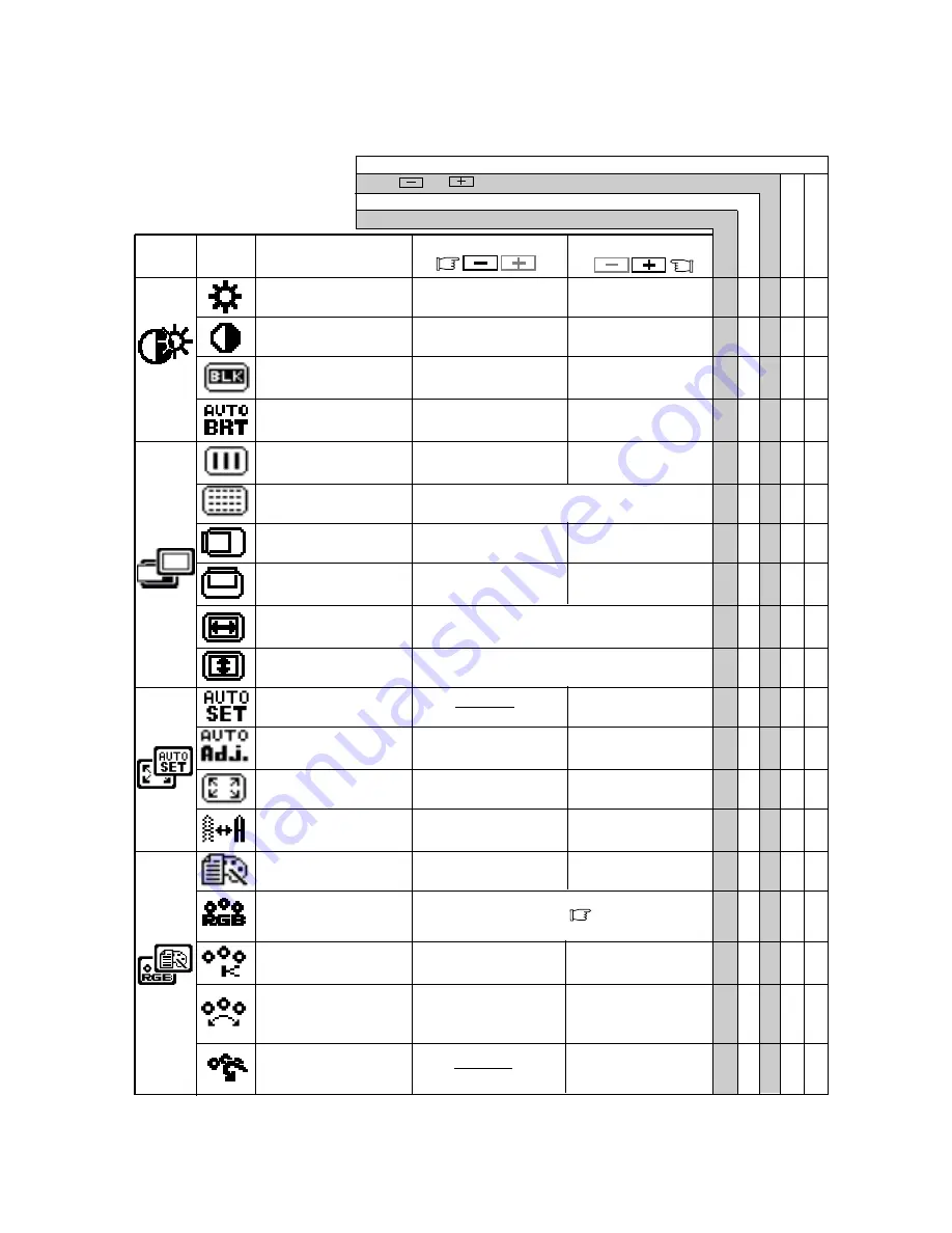
Press         and          buttons together, to restore to the factory preset level.

Press "ALL RESET" to restore to the factory preset level.

To be deep of black
color.

To be light of black
color.

To move the image to
the left.

To move the image
to the right.

To move the image
down.

To move the image
up.

To display by TEXT
mode.

To restore to the color tem-
perature and color control to
the factory preset.

To adjust the height of the image on the screen.

To adjust the width of the image on the screen.

Group

Icon

Press the Minus Button:

Press the Plus Button:

Item
Icon

Item

T o   d e c r e a s e   t h e
brightness.

T o   i n c r e a s e   t h e
brightness.

To decrease the con-
trast.

To increase the con-
trast.

To display by  GRAPHIC
mode.

Set data by each timing.

Set data does not change by the changing of the signal timing.

To conduct Auto Setup.

To off the Auto Bright
Function.

To on the Auto Bright
Function.

To narrow the width of

the image on the screen

to the left.

To change the snow noise of the image.

To expand the width

of the image on the

screen to the right.

5.1

Adjustment Items

To decrease the color
temperature.

To increase the color
temperature.

To off the Auto Adjust-
ment Function.

To on the Auto Adjust-
ment Function.

Factory Presets

User Presets

Select the desired Color from sRGB, VIDEO
NATIVE and CUSTOM.  (        P1-4)
(sRGB, VIDEO, NATIVE: Unadjustable.)

To decrease the
distinction.

To increase the
distinction.

The color of screen is
adjusted to the "-"
symbol's color at Level-
bar's left side.

The color of screen is
adjusted to the "+"
symbol's color at Level-
bar's right side.

To set the normal screen
area.

To set the expanded
screen area.

BRIGHTNESS

○ ○ ○

CONTRAST

○ ○ ○

BLACK LEVEL

○ ○ ○

AUTO BRIGHTNESS

○ ○

CLOCK

CLOCK PHASE

HORIZONTAL POSITION

VERTICAL POSITION

H RESOLUTION

V RESOLUTION

AUTO SETUP

AUTO ADJUST

EXPAND

 SHARPNESS

○ ○

DISPLAY MODE

○ ○

COLOR

○ ○

COLOR TEMPERATURE

○ ○ ○

COLOR CONTROL

○ ○ ○

COLOR RESET

Summary of Contents for MultiSync LCD1800

Page 1: ...RIAL No The serial number is located on the rear cover of the monitor AUTO SCANNING WITH DIGITAL CONTROL LCD COLOR DISPLAY MONITOR MultiSync LCD1800 SELECT ADJUST OSD OFF SIGNAL A B Supplying Windows 95 98 INF File download service new products information etc Internet Home Page http www necmitsubishi com ...

Page 2: ...ITSUBISHI ELECTRIC VISUAL SYSTEMS CORPORATION makes no representa tions to the contrary Life support devices are those devices which are used to measure diagnose or evaluate the tissue systems or functions of the human body or other devices employed to support or sustain life or good health 1 INTRODUCTION 1 2 1 1 Features 1 2 1 2 Internal Preset Memory Capability 1 2 1 3 IPM Intelligent Power Mana...

Page 3: ...to which the receiver is con nected Consult the dealer or an experienced radio TV tech nician for help NO USER SERVICEABLE PARTS IN SIDE DO NOT ATTEMPT TO MODIFY THIS EQUIPMENT IF MODIFIED YOUR AUTHORITY TO OPERATE THIS EQUIP MENT MIGHT BE VOIDED BY FCC この装置は 情報処理装置等電波障害自主規制協議会 VCCI の基準に基づくクラスB情報技術装置です この装置 は 家庭環境で使用することを目的としていますが この 装置がラジオやテレビジョン受信機に近接して使用される と 受信障害を引き起こすことがあります 取扱説明書に従って正しい取り扱いを...

Page 4: ...sability Below you will find a brief summary of the environmental requirements met by this product The complete environmental criteria document may be ordered from TCO Development SE 114 94 Stockholm Sweden Fax 46 8 782 92 07 Email Internet development tco se Current information regarding TCO 99 approved and labelled products may also be obtained via the Internet using the address http www tco inf...

Page 5: ...Manager System Provides innovative power saving methods that allow the monitor to shift to a lower power consumption level when on but not in use saving two thirds of your monitor energy costs reducing emissions and lower ing the air conditioning costs of the workplace Multiple Frequency Technology Automatically adjusts monitor to the display card s scanning frequency thus displaying the resolutio...

Page 6: ... of 1024 dots by 768 lines or lower is inputted to the monitor With some resolution even if it meets the condition above the screen is not expanded fully to the screen area With some signal type inputted the screen is not expanded vertically or horizontally With some resolution the image may be slightly blurred 1 8 Signal Input Connector Auto Selection Func tion AUTO SELECT P1 11 This function is ...

Page 7: ...he power cord can cause a fire or electrical shock When transporting the monitor handle it with care Avoid giving any shock or scratch to the screen as the screen is fragile 1 12 Cleaning Your Monitor When clean the monitor please follow these guidelines Always unplug the monitor before cleaning Wipe the screen and cabinet front and sides with a soft cloth Do not spray directly on the screen as ex...

Page 8: ... 1 15 Quick Operation Chart To summarize the steps in connecting your computer and adapter with MultiSync LCD1800 color LCD monitor and setting the necessary controls and switches refer to the chart below Connect the power cord to the MultiSync LCD1800 color LCD monitor and the signal cable between the MultiSync LCD1800 and the computer Set the controls and switches ...

Page 9: ...s Under the OSM off condition Push to select the signal input connector which is connected to the computer which you want to use Under the OSM on condition Push to turn off OSM FUNCTION SELECT BUTTONS Push the select buttons to choose one of the functions that is superimposed on the display screen FUNCTION ADJUST BUTTONS Push the adjust buttons to adjust the image on the screen that is selected vi...

Page 10: ...monitor then the computer On the back of the monitor are three plug in connec tions one for the DC power connection and others for the video signal connection 3 1 AC Power Connection Remove the cable covers The DC jack from the AC Adapter is connected into the DC power connector on the back of the monitor One end of the power cord is connected into the AC Adapter and another end of the power cord ...

Page 11: ...Computer Apple Macintosh Computer Signal Cable 3 2 2 Connecting to An Apple Macintosh Computer Figure 6 shows the signal cable and Macintosh Adapter to the video port in an Apple Macintosh 1 Power off both the monitor and the computer 2 Connect the 15 pin D SUB 15P end of the Macintosh Adapter to the straight 15 pin connector on the Macintosh video port on the computer or on the video board 3 Conn...

Page 12: ... the monitor is used with an interlace signal of resolution 1280 dots by 1024 lines one line in the top or bottom of the screen is lost This condition can not be corrected by any adjustment Conduct the AUTO SETUP according to the following procedure 1 Turn on the computer and monitor If you don t recognize the icon on the screen adjust CLOCK until you can with using the OSM Function If you don t s...

Page 13: ... Auto Bright Function To on the Auto Bright Function To narrow the width of the image on the screen to the left To change the snow noise of the image To expand the width of the image on the screen to the right 5 1 Adjustment Items To decrease the color temperature To increase the color temperature To off the Auto Adjust ment Function To on the Auto Adjust ment Function Factory Presets User Presets...

Page 14: ...ate OSM again 5 2 CONTROL LOCK Mode Operation ADJUST ADJUST SELECT ADJUST Press and buttons together to restore to the factory preset level Press ALL RESET to restore to the factory preset level Group Icon Press the Minus Button Press the Plus Button Item Icon Item Set data by each timing Set data does not change by the changing of the signal timing Factory Presets User Presets ALL RESET OSD POSIT...

Page 15: ...n is active Input signal frequency range is out of specification Display Resolution is out of range Signal cable disconnected Computer power switch Power management function is active Adjust RESOLUTION CLOCK CLOCK PHASE H POSITION and V POSITION with non standard signals Monitor may not be able to get full screen image depending on signal In this case please select other resolution or other vertic...

Page 16: ...m 2 Typ SIGNAL INPUT CONNECTORS D SUB 15P One is with the detachable signal cable and another is behind the cable cover OPERATING Temperature 5 35 C ENVIRONMENT Humidity 10 90 RH without condensation POWER SOURCE Display Monitor 55W MAX AC Adapter INPUT AC100 240V 10 50 60Hz OUTPUT DC15V Safety UL1950 UL CSA C22 2 No 950 C UL EN60950 TÜV GS EMC FCC Class B DOC Class B EN55022 Class B EN50082 1 VCC...

Page 17: ... NEC MITSUBISHI for service MUST have prior approval which may be obtained by calling 1 800 632 4662 The Product shall not have been previously altered re paired or serviced by anyone other than a service facility authorized by NEC MITSUBISHI to render such service the serial number of the product shall not have been altered or removed In order to be covered by this warranty the Product shall not ...

Page 18: ...mettent de mesurer d évaluer ou d assurer le bon fonctionnement des fonctions du corps humain NEC MITSUBISHI ELECTRIC VISUAL SYSTEMS CORPORATION ne peut en aucun cas être tenu responsable en cas d utilisation de ce produit sur de tels systèmes TABLE DES MATIERES 1 INTRODUCTION 2 2 1 1 Caractéristiques 2 2 1 2 Valeurs préréglées stockées en mémoire 2 2 1 3 IPMMC Intelligent Power Manager System 2 3...

Page 19: ...Système IPMMC Intelligent Power Manager Fournit des méthodes innovantes d économie d énergie qui permettent au moniteur de passer dans un mode à faible consommation électrique lorsqu il est sous tension sans être utilisé ce qui économise les deux tiers du coût de la consommation électrique du moniteur réduit les émissions et diminue le coût de la climatisation de la salle 1 INTRODUCTION Technologi...

Page 20: ...r d énergie Lorsque le signal de synchronisation horizontale et ou le signal de synchronisation verticale sont inactifs après 10 secondes environ le moniteur bascule en mode économiseur d énergie sa consommation en puissance est alors inférieure à 3W Lorsque le moniteur est dans le mode économiseur d énergie l écran est noir et le voyant d alimentation est de couleur ambre Dés que les signaux sont...

Page 21: ...UR Pour restaurer le réglages de la température et du contrôle des couleurs au réglages usines 1 11 Considérations relatives à l emplacement du moniteur Lors de la mise en place et lorsque vous utilisez votre moniteur gardez en mémoire ces quelques règles Pour garantir une vision optimale éviter d installer votre moniteur face à un arrière plan lumineux ou à un endroit où la lumière solaire ou d a...

Page 22: ...s pré réglages par les switches et les réglages Connecter le cordon d alimentation du MultiSync LCD1800 ainsi que le câble vidéo entre le moniteur couleur et l unité centrale 1 15 Processus de mise en route Pour assurer la connexion les pré réglages par les switches et les réglages du moniteur MultiSync LCD1800MC à votre ordinateur veuillez suivre le proces sus suivant ...

Page 23: ...r sélectionner l entrée vidéo sur laquelle l unité centrale est raccordée Lorsque le Menu à l écran est visible Presser le bouton pour faire disparaître le Menu à l écran TOUCHES DE SÉLECTION DES FONCTIONS Appuyer sur ces touches pour choisir une des fonctions qui s affichera en incrustation à l écran SIGNAL A B SELECT ADJUST OSD OFF 2 GLOSSAIRE Figure 3 Figure 4 ARRIÈRE TOUCHES DE RÉGLAGE Appuyer...

Page 24: ...on qui correspond à la tension de l alimentation fournie à la prise de courant CA Le cordon d alimentation utilis é doit être agréé et en conformit é avec les normes de sécurité de son pays 3 2 Branchement des câbles véhiculant les signaux Le câble vidéo fourni comporte un connecteur D SUB 15P pour les sorties analogiques RVB compatibles VGA de votre PC Une unité centrale de type Macintosh peut êt...

Page 25: ...isation du système éteindre l ordinateur puis ensuite le moniteur Pour un Apple Macintosh muni d un port compatible VGA l étape 2 à 4 ne sont pas nécessaires Connectez le câble du signal directement sur le port 3 2 3 Connexion de 2 unités centrales La Figure 7 montre la connexion des cables de signal d entrée à 2 unités centrales 1 Eteindre le moniteur et les unités centrales 2 Connectez une extré...

Page 26: ...ion Effectuer le REGLAGES AUTO suivant le procédure suivante 1 Mettre le moniteur puis l unité centrale sous tension Si les icônes n apparaissent pas clairement alors régler HORLOGE en utilisant le MENU A L ECRAN Si vous ne pouvez apercevoir les icônes parce que l image n est pas correctement centrée dans la posi tion horizontale ou verticale alors régler POSITION VERTICALE ou POSITION HORIZONTALE...

Page 27: ...l écran vers la droite Permet de déplacer l image vers le bas Permet de déplacer l image vers le haut Pour revenir au mode de réglage usine Affiche le mode texte A f f i c h e l e m o d e graphique Pour inhiber la fonction d Auto luminosité Pour opérer le fonction d Auto luminosité Pour diminuer la distinction Pour augmenter la distinction Pour régler la hauteur de l image Pour régler la taille ho...

Page 28: ...sez un Macintosh anciennegénération vous devez presser le bouton Plus ADJUST ADJUST SELECT ADJUST Mémorisation usine Mémorisation utilisater Presser les touches et simultanément ramène au réglage memorisé en usine Appuyer RÉGLAGES USINE pour revenir à la configuration d usine Fixe les valeurs pour chaque timing Les valeurs fixées ne sont pas affectées pas un changement de timing LUMINOSITÉ LUMINOS...

Page 29: ... PO SITION HORIZONTALE et POSITION VERTICALE avec un signal non standard Le moniteur peut ne pas obtenir une image plein écran selon le signal Dans ce cas sélectionner une autre résolution ou une autre fréquence de rafraîchissement écran Régler la taille à la position horizontales et verticales attendez quelques secondes après avoir effectué le réglage de la taille avant de déconnecter ou d eteind...

Page 30: ...cd m2 Typ CONNECTEUR D ENTRÉE SIGNAUX D SUB 15P Un avec un câble de signal détachable et l autre est dérrière le couvercle des câbles CONDITION DE Température 5 35 C FONCTION Hygrométrie 10 90 RH sans condensation ALIMENTATION Moniteurs LCD 55W MAX Adaptateur AC ENTREE AC100 240V 10 50 60Hz SORTIE DC15V Sécurité UL1950 UL CSA C22 2 No 950 C UL EN60950 TÜV GS EMC FCC Classe B DOC Classe B EN55022 C...

Page 31: ...s devez d abord obtenir une autorisation de retour de marchandise en composant le 1 800 632 4662 Le produit ne pourra avoir été enlevé ou modifié réparé ou entretenu au préalable par personne d autre que du personnel technique autorisé par NEC MITSUBISHI et le numéro de série du produit ne pourra pas avoir été enlevé Pour être couvert par cette garantie le produit ne pourra pas avoir été soumis à ...

Page 32: ...UNUNG Wir NEC MITSUBISHI ELECTRIC VISUAL SYSTEMS CORPORATION erklären in alleiniger Verantworlung daß das Produkt auf das sich diese Erklärung bezieht mit der den folgenden Normen oder normativen Dokumenten übereinstimmt EN60950 EN55022 Klasse B EN50082 1 EN61000 3 3 Gemäß den Bestimmungen der Richtlinien 73 23 EEC Niederspannungsrichtlinie 89 336 EEC EMV Richtlinie ACHTUNG Dieses Produkt ist nich...

Page 33: ...tellt wird IPMTM System Intelligent Power Manager Der Intelligent Power Manager intelligenter Energieverwalter ist eine fortschrittliche Einrichtung zum Energiesparen Bei Arbeitspausen am LCD Moni tor werden 2 3 an Energiekosten eingespart Wärmeemissionen reduziert wodurch der Klimatisierungsaufwand am Arbeitsplatz geringer wird Multi Frequenz Technologie Die Multi Frequenz Technologie hat die Eig...

Page 34: ...RKUNG I m A u s l i e f e r z u s t a n d i s t d i e F u n k t i o n ANZEIGEMODUS auf GRAFIK eingestellt Führen Sie bitte die Funktion AUTOEINSTELLUNG durch bevor Sie den Modus GRAFIK auswählen Ansonsten könnte der Bildschirm zu hell werden Bevor Sie eine Farbkalibrierung durchführen setzen Sie bitte die Funktion FARBE auf NATIVE und ANZEIGEMODUS auf GRAFIK S 3 10 1 6 Automatische Korrekturfunkti...

Page 35: ...euchtigkeit und Staub um einen Brand oder Stromstöße zu vermeiden Achten Sie darauf daß weder der Monitor noch ein anderer schwerer Gegenstand auf dem Netzkabel stehen Eine Beschädigung des Netzkabels kann einen Brand oder Stromstöße verursachen Behandeln Sie den Monitor vorsichtig beim Transport Vermeiden Sie jede Art von Stößen oder Kratzern da der Bildschirm zerbrechlich ist 1 12 Reinigung lhre...

Page 36: ...UNGSSUCHE Schalten Sie den Computer ein Schalten Sie den MultiSync LCD1800 Monitor ein Stellen Sie den Monitor nach lhren Bedüfnissen ein Bei Auftreten eines Problems Läßt sich das Problem nicht beheben Wenden Sie sich an den autorisierten Product Support Schließen Sie das Netzkabel an den MultiSync LCD1800 Farb LCD Monitor an und verbinden Sie mit das Signalkabel mit den MultiSync LCD1800 und den...

Page 37: ...HALTER Schaltet das Gerät ein bzw aus BETRIEBSANZEIGE Diese Anzeige leuchtet auf wenn der Monitor eingeschaltet ist SIGNAL A B und OSD OFF Taste Diese Taste hat die folgenden zwei Funktionen Falls das OSM nicht aktiv ist Drücken Sie diese Taste um den Signaleingang umzuschalten Falls das OSM aktiv ist Drücken Sie diese Taste um das OSM abzuschalten AUSWAHLTASTEN FÜR EINSTELLFUNKTIONEN Mit der rech...

Page 38: ...der v e r w e n d e t e n Wechselstromsteckdose entspricht Das verwendete N e t z k a b e l m u ß d e n Sicherheitsnormen Ihres Landes entsprechen und gemäß dieser zugelassen sein 3 2 Anschluß des Signalkabels Das beigefügte Signalkabel ist mit einem D SUB 15P Stecker für den Anschluß an die VGA kompatiblen analogen RGB Ausgänge lhres PC ausgestattet Der Anschluß von Apple Macintosh Computem kann ...

Page 39: ...A kompatiblen Anschluß ausgestattet ist entfallen die Schritte 2 bis 4 Schließen Sie in diesem Fall das Signalkabel direkt an Anschluß an 3 2 3 Anschluß an zwei Computer Bild 7 zeigt den Anschluß der Signalkabel an zwei Com puter 1 Schalten Sie den Monitor und die Computer aus 2 Schließen Sie das Ende des fest verbundenen Signalkabels an den 15 poligen Anschluß des einen Computers an 3 Zum Anschlu...

Page 40: ...ierung nicht behoben werden Führen Sie die AUTOEINSTELLUNG folgendermaßen durch 1 Schalten Sie den Computer und den Monitor ein ANMERKUNG Falls Sie das Symbol nicht erkennen können ändern Sie TAKT bis es erkennbar ist Falls Sie das Symbol nicht sehen können weil das Bild in vertikaler oder horizontaler Richtung verschoben ist stellen Sie bitte VERTIKALE BILDLAGE oder HORIZONTALE BILDLAGE mit Hilfe...

Page 41: ...n Um das Bild nach links zu verschieben Um das Bild nach rechts zu verschieben Um das Bild nach unten zu verschieben Um das Bild nach oben zu verschieben Um das Rauschen Schnee des Bildes zu verringern Führt AUTOEIN STELLUNG durch Wählt den Anzeige modus TEXT aus Wählt den Anzeige modus GRAFIK aus Schaltet die Funktion AUTOM KORREKTUR aus Schaltet die Funktion AUTOM HELLIGKEIT aus Schaltet die Fun...

Page 42: ...UNG um diese Funktionen auf die werksseitigen Voreinstellungen zurückzusetzen Diese Einstellungen sind unabhängig vom verwendeten Timing und ändern sich beim Wechsel des Videosignals nicht Diese Werte müssen für jedes Timing einzeln eingestellt werden Gruppen symbol Drücken Sie die Minus Taste Symbol Drücken Sie die Plus Taste Funktion SCHWARZWERT KLEMMUNG HELLIGKEIT HELLIGKEIT 5 2 Benutzung der O...

Page 43: ...s Computers eingeschaltet Energiesparfunktion ist aktiv Eingangssignalfrequenz außerhalb des zulässigen Bereichs Die Auflösung befindet sich außerhalb des zulässigen Bereichs Signalkabel angeschlossen Netzschalter des Computers eingeschaltet Energiesparfunktion ist aktiv Bei User Timing AUFLÖSUNG TAKT TAKTPHASE HORIZONTALE BILDLAGE und VERTIKALE BILDLAGE einstellen Im Einzelfall kann es vorkommen ...

Page 44: ...HELLIGKEIT bei voller Weißfläche 200 cd m2 Typ EINGANGSANSCHLUß D SUB 15P Einmal fest angeschlossenes Signalkabel einmal Buchse hinter der Abdeckklappe BETRIEBS Temperature 5 35 C BEDINGUNGEN Feuchtigkeit 10 90 rel Luftf nicht kondensierend NETZSPANNUNG Farbmonitor 55W max AC Adapater EINGANG AC100 240V 10 50 60Hz AUSGANG DC15V Sicherheit UL1950 UL CSA C22 2 No 950 C UL EN60950 TÜV GS EMC FCC Klas...

Page 45: ...hten oder liefern zu lassen Produkte dürfen nur nach vorheriger Genehmigung zu Servicezwecken an NEC MITSUBISHI übermittelt werden Diese Genehmigung ist unter der Telefonnummer 1 800 632 4662 einzuholen Das betreffende Produkt darf zuvor lediglich von Serviceeinrichtungen die von NEC MITSUBISHI zur Erbringung derartiger Leistungen autorisiert wurden verändert repariert oder gewartet worden sein Di...

Reviews: