background image

English

English-3

Contents

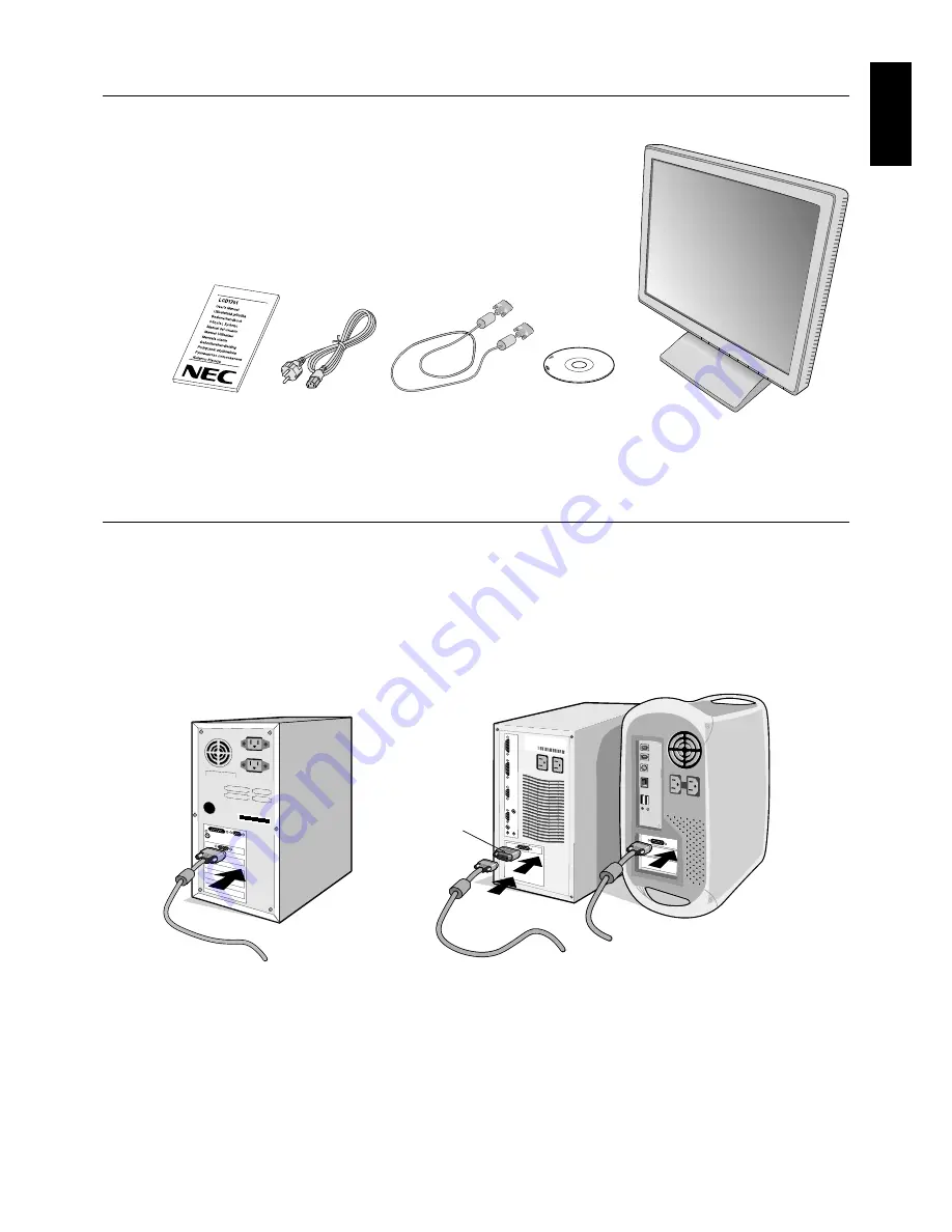
Your new NEC LCD monitor box* should contain the following:

LCD1701 monitor with tilt base

Power Cord

Video Signal Cable

User’s Manual

CD ROM (includes complete User’s Manual in PDF format).
To see the User’s Manual, Acrobat Reader 4.0 must be installed on your PC.

*

Remember to save your original box and packing material to transport or ship the monitor.

Quick Start

To attach the LCD monitor to your system, follow these instructions:

1. Turn off the power to your computer.

2. Remove cable cover.

3.

For PC:

 Connect the 15-pin mini D-SUB of the appropriate signal cable to the connector for the display card in your

system (

Figure A.1

). Tighten all screws.

For Mac:

 Connect the LCD1701 Macintosh cable adapter to the computer (

Figure B.1

). Attach the 15-pin mini D-SUB end

of the appropriate signal cable to the LCD1701 Macintosh cable adapter (

Figure B.1

). Tighten all screws.

Figure A.1

Figure B.1

Macintosh
Cable Adapter
(not included)

Macintosh G3 and G4
do not need a Macintosh
cable adapter

4. Connect the 15-pin mini D-SUB of the video signal cable to the appropriate connector on the back of the monitor

(

Figure C.1

).

5. Connect one end of the power cord to the LCD1701 monitor and the other end to the power outlet. Place the video signal

cable and AC power cord under the cable cover (

Figure C.1

). Replace cable cover.

NOTE:

Adjust the position of the cable under the cable cover to avoid damage for cable or monitor.
As indicated (

Figure C.1

) please adjust the cables to place the ferrite core and stopper above the cubic cover.

NOTE:

Please refer to Caution section of this manual for proper selection of AC power cord.

Summary of Contents for MultiSync LCD1701

Page 1: ...LCD1701 User s Manual ...

Page 2: ...not represent EPA endorsement of any product or service ErgoDesign is a registred trademark of NEC Mitsubishi Electric Visual Systems Corporation in Austria Benelux Denmark France Germany Italy Norway Spain Sweden U K IBM PC XT AT PS 2 MCGA VGA 8514 A and XGA are registered trademarks of International Business Machines Corporation Apple and Macintosh are registered trademarks of Apple Computer Inc...

Page 3: ...adio communications However there is no guarantee that interference will not occur in a particular installation If this equipment does cause harmful interference to radio or television reception which can be determined by turning the equipment off and on the user is encouraged to try to correct the interference by one or more of the following measures Reorient or relocate the receiving antenna Inc...

Page 4: ...able adapter to the computer Figure B 1 Attach the 15 pin mini D SUB end of the appropriate signal cable to the LCD1701 Macintosh cable adapter Figure B 1 Tighten all screws Figure A 1 Figure B 1 Macintosh Cable Adapter not included Macintosh G3 and G4 do not need a Macintosh cable adapter 4 Connect the 15 pin mini D SUB of the video signal cable to the appropriate connector on the back of the mon...

Page 5: ...he front button DO NOT switch on off repeatedly 7 No touch Auto Adjust automatically adjusts the monitor to optimal settings upon initial setup for most timings For further adjustments use the following OSM controls Auto Adjust Contrast Auto Adjust Refer to the Controls section of this User s Manual for a full description of these OSM controls NOTE If you have any problems please refer to the Trou...

Page 6: ...ive surface Figure R 1 3 Remove the hinge cover Figure R 1 4 Remove the 4 screws connecting the monitor to the stand and lift off the stand assembly Figure R 2 the monitor is now ready for mounting in an alternate manner 5 Connect the AC cord and signal cable to the back of the monitor Figure R 3 6 Reverse this process to reattach stand NOTE Use only VESA compatible alternative mounting method Han...

Page 7: ...n arm which guaranties the necessary stability under consideration of the weight of the monitor The LCD monitor shall only be used with an approved arm e g GS mark Figure R 3 4 SCREWS M4 MAX depth 8 5 mm If use other screw check depth of hole Weight of LCD assembly 4 6kg MAX Replace screws Tighten all screws 100 mm 100 mm Thickness of bracket arm 2 0 3 2 mm Specifications Figure R 2 ...

Page 8: ...splay area of the LCD H SIZE Adjusts the horizontal size by increasing or decreasing this setting Should the AUTO Adjust function do not give you a satisfactory picture setting a further tuning can be performed using the H Size function dot clock For this a Moiré test pattern could be used This function may alter the width of the picture Use Left Right Menu to center the image on the screen If the...

Page 9: ...ages OSM POSITION You can choose where you would like the OSM control image to appear on your screen Selecting OSM Location allows you to manually adjust the position of the OSM control menu left right down or up OSM TURN OFF The OSM control menu will stay on as long as it is use In the OSM Turn Off submenu you can select how long the monitor waits after the last touch of a button to shut off the ...

Page 10: ...it button NO SIGNAL This function gives a warning when there is no signal present After power is turned on or when there is a change of input signal or video is inactive the No Signal window will appear RESOLUTION NOTIFIER This function gives a warning of use with optimized resolution After power is turned on or when there is a change of input signal or the video signal doesn t have proper resolut...

Page 11: ...er heat sources Do not put anything on top of monitor The power cable connector is the primary means of detaching the system from the power supply The monitor should be installed close to a power outlet which is easily accessible Handle with care when transporting Save packaging for transporting Image Persistence Image persistence is when a residual or ghost image of a previous image remains visib...

Page 12: ...t 70 70 Contrast Ratio 10 1 80 80 Contrast Ratio 5 1 Up Down 60 60 Contrast Ratio 10 1 65 75 Contrast Ratio 5 1 Resolutions Supported 720 x 400 1 VGA text Some systems may not 640 x 480 1 at 60 Hz to 75 Hz support all modes listed 800 x 600 1 at 56 Hz to 75 Hz 832 x 624 1 at 75 Hz 1024 x 768 1 at 60 Hz to 75 Hz 1152 x 870 1 at 75 Hz 1280 x 1024 2 at 60 Hz to 75 Hz Active Display Area Horizontal 33...

Page 13: ...justments tilt base for preferred angle of vision small footprint and compliance with MPRII and TCO guidelines for lower emissions Plug and Play The Microsoft solution with the Windows 95 98 Me 2000 XP operating system facilitates setup and installation by allowing the monitor to send its capabilities such as screen size and resolutions supported directly to your computer automatically optimizing ...

Page 14: ...NOTE As with all personal display devices NEC Mitsubishi Electronic Displays recommends using a screen saver at regular intervals whenever the screen is idle Image is unstable unfocused or swimming is apparent Signal cable should be completely attached to the computer Use the OSM Image Adjust controls to focus and adjust display by increasing or decreasing the fine total When the display mode is c...

Page 15: ...t environmental demands for example in respect of the reduction of electric and magnetic fields physical and visual ergonomics and good usability Environmental Requirements Flame retardants Flame retardants are present in printed circuit boards cables wires casings and housings In turn they delay the spread of fire Up to thirty percent of the plastic in a computer casing can consist of flame retar...

Reviews: