background image

English-10

8. Reverse this process to re-attach stand.

NOTE:

Use only VESA-compatible alternative mounting method.
Handle with care when removing stand.

NOTE:

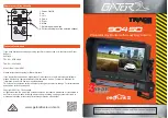
Match “TOP SIDE” mark on stand to top side of the monitor head when
re-attaching stand.

Flexible Arm Installation

This LCD monitor is designed for use with a flexible arm. To mount the monitor to a flexible arm:

1. Follow the instructions on how Remove Monitor Stand for Mounting to remove the stand.

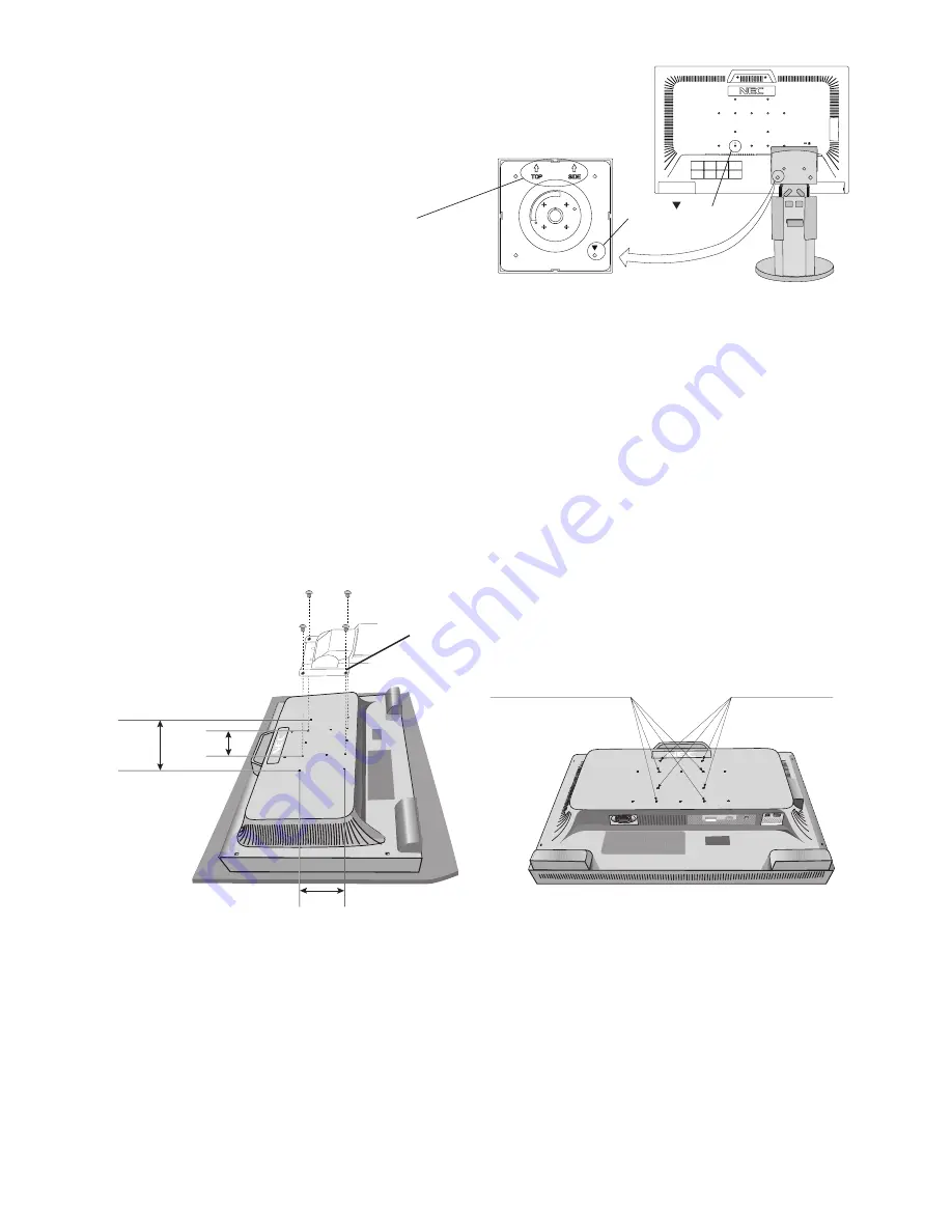
2. Using the 4 screws from the stand removal, attach the arm to the monitor (

Figure F.1

).

NOTE:

1. When mounting, use ONLY the screws (4 pcs) that were removed from the stand to avoid damage to the monitor
or stand.

2. The LCD monitor should only be used with an approved arm (e.g. GS mark). To meet the safety requirements,
the monitor must be mounted to an arm, which guaranties the necessary stability under consideration of the weight
of the monitor.

3. When using mounting accessories (e.g. VESA (200 x 100)) other than VESA (100 x 100), use M4 size screws
(Length: bracket thi 10mm).

4. The mounting stand must be able to sustain at least 34 kg and be UL certified.

Thickness of Bracket (Arm)

2.0~3.2 mm

Weight of LCD assembly: 8.5 kg MAX

200 mm

100 mm

Figure F.1

4 Screws (M4)

(Max Depth: 10.8 mm)

Hole of “

” mark

Please assemble

then together

100 mm

An additional 4 VESA holes are provided for those users needing a lower monitor head position, than that available from the
monitor stand in shipping configuration.
The monitor stand can be re-attached using the 4 screws to the lower position VESA holes.

NOTE:

1. The monitor head tilt function may have impaired operation when attached to the lower position VESA holes.
2. The monitor head pivot function should not be used when attached to the lower position VESA holes.

“TOP SIDE” mark

Please match top side

of the monitor

Additional 4 VESA

Summary of Contents for MultiSync EA261WM

Page 1: ...MultiSync EA261WM User s Manual...

Page 2: ...sh 1 Recommended use English 3 Contents English 5 Quick Start English 6 Controls English 11 Specifications English 14 Features English 15 Troubleshooting English 16 Appendix English 16 TCO 03 English...

Page 3: ...GE COMPONENTS INSIDE REFER SERVICING TO QUALIFIED SERVICE PERSONNEL Declaration of the Manufacturer We hereby certify that the colour monitor MultiSync EA261WM L267HM is in compliance with Council Dir...

Page 4: ...receiver is connected Consult your dealer or an experienced radio TV technician for help If necessary the user should contact the dealer or an experienced radio television technician for additional su...

Page 5: ...as been dropped or the cabinet damaged If the monitor does not operate normally by following operating instructions If glass is broken handle with care If monitor or glass is broken do not come in con...

Page 6: ...image persistence after image effects Get regular eye checkups Ergonomics To realize the maximum ergonomics benefits we recommend the following Adjust the Brightness until the background raster disapp...

Page 7: ...SUB male to 15 pin mini D SUB male Video Signal Cable DVI D to DVI D USB Cable Audio Cable Setup Manual Power Cord Type of power cord included will depend on the where the LCD monitor is to be shippe...

Page 8: ...ble Adapter not included Figure A 2 DVI signal cable Figure C 1a A Type B Type A Type B Type NOTE Some Macintosh systems do not require a Macintosh cable adapter 3 Place hands on each side of the moni...

Page 9: ...cated in Figure C 2 Figure C 3 6 Make sure all cables are resting flat against the stand Figure C 2 Figure C 3 Please check Tilt Rise and Lower monitor screen and screen rotation when you manage cable...

Page 10: ...t Analog input only Auto Adjust Analog input only Refer to the Controls section of this User s Manual for a full description of these OSD controls NOTE If you have any problems please refer to the Tro...

Page 11: ...the monitor Figure S 2 NOTE In order to avoid stand drop when removing screws please support stand with your hand Screen Rotation Before rotating the screen must be raised to the highest level to avoi...

Page 12: ...uaranties the necessary stability under consideration of the weight of the monitor 3 When using mounting accessories e g VESA 200 x 100 other than VESA 100 x 100 use M4 size screws Length bracket thic...

Page 13: ...onsumed by reducing the brightness level OFF Set brightness variable from 0 to 100 ON Set brightness variable range from 0 to 50 When this function is set to ON a bar for CARBON FOOTPRINT appear under...

Page 14: ...the Blue LED brightness INPUT RESOLUTION Analog Input Only Selects resolution s priority of input signal to one of the following pair 1360 x 768 1680 x 1050 or 1280 x 768 1680 x 1050 or 1024 x 768 140...

Page 15: ...carbon footprint factor in the carbon saving calculation is based on the OECD 2006 Edition OSD Warning OSD Warning menus disappear with Exit button NO SIGNAL This function gives a warning when there...

Page 16: ...for optimal display performance Active Landscape Horiz 560 mm 22 1 inches Display Area Vert 350 mm 13 8 inches Portrait Horiz 350 mm 13 8 inches Vert 560 mm 22 1 inches USB Hub I P USB Specification...

Page 17: ...perating system facilitates setup and installation by allowing the monitor to send its capabilities such as screen size and resolutions supported directly to your computer automatically optimizing dis...

Page 18: ...hour to erase the image NOTE As with all personal display devices NEC DISPLAY SOLUTIONS recommends displaying moving images and using a moving screen saver at regular intervals whenever the screen is...

Page 19: ...rgy Energy saving mode after a certain time beneficial both for the user and the environment Electrical safety Emissions Electromagnetic fields Noise emissions Ecology The product must be prepared for...

Page 20: ...p www nec display com in Japan or http www necdisplay com in USA Energy Saving This monitor features an advanced energy saving capability When a VESA Display Power Management Signalling DPMS Standard...

Reviews: