background image

16:9 Screens 

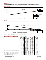
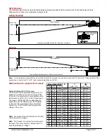
The following diagram shows the relationship between projector position and the screen. Refer to the chart below for data. 
Distances are in inches. For millimeters multiply by 25.4. 
 

Ceiling Mounted 


Throw Distance


Screen Top

B

α

Lens Offset from
Mount Pipe


Screen Ctr


C

* lens set back inside shroud 0.4" from front of cabinet

/ Lens Ctr*

4.4"

2.9"

4.4"


Desktop 


www.necvisualsystems.com 


Page 3 of 7 


C

Throw Distance

B

Screen Ctr

3.1"

α

* lens set back inside shroud 0.4" from front of cabinet

Screen Bottom

/ Lens Ctr*

Note:  To avoid premature lamp failure, do not tilt the front of the projector up or down by more than 75° from level. Tilting the front of the 
projector up or down from 15° to 75° might reduce lamp life by up to 25%. 


Distance chart for popular 16:9 screens 

B

Diag

W

H

wide - tele

wide - tele

inches

inches

inches

inches

82.6

72

40.5

27.0

191.0 - 303.3

8.0 - 5.1

92

80

45

30.0

212.8 - 337.6

8.0 - 5.1

100

87

49

32.6

231.9 367.6

8.0 5.1

106

92

52

34.5

245.6 389.0

8.0 5.1

110

96

54

36.0

256.5 - 406.1

8.0 - 5.1

119

104

58.5

39.0

278.3 - 440.4

8.0 - 5.1

123

107

60

40.1

286.4 - 453.3

8.0 - 5.1

133

116

65

43.5

311.0 - 491.9

8.0 - 5.1

135

118

66

44.3

316.4 - 500.4

8.0 - 5.1

159.5

139

78

52.1

373.7 - 590.5

7.9 - 5.0

161

140

79

52.5

376.4 - 594.7

7.9 - 5.0

229.5

200

112.5

75.0

540.0 - 851.9

7.9 - 5.0

275

240

135

90.0

649.1 - 1023.4

7.9 - 5.0

321

280

157.5

105.0

758.1 - NA

7.9 - NA

367

320

180

120.0

867.2 - NA

7.9 - NA

459

400

225

150.0

1085.3 - NA

7.9 - NA

Screen Size (16:9)

C

inches

α

degrees


Vertical Position for a 16:9 screen  
The Vertical Position adjustment moves the 16:9


image up and down in the unused portion of the 
4:3 panel. This adjustment is only available when 
the projector is set for ‘16:9’ in the 

Screen’ menu. 

The range of Vertical Position is dependent on 
aspect ratio and 3D Reform used. If 3D Reform 
is not used, the approximate range of Vertical 

P

osition is +/-0.167H (H=Screen Height) when 

using a 16:9 screen.


Note:  For screen sizes not indicated on the chart, 
use the formulas on page 1. 


Note:  “NA” means it is outside the lens range for 
that part of the zoom. Refer to “Screen Sizes” in 
Lens Specifications on Page 1. 


Summary of Contents for MT1065 - MultiSync XGA LCD Projector

Page 1: ...ts of the formulas use the values in the chart The ceiling must be strong enough to support the projector and the installation must be in accordance with any local building codes Distances are in inches for millimeters multiply by 25 4 Distances may vary 5 Formulas The Projection Formulas use the image width for calculation Image width is the same for all aspect ratios only vertical image size var...

Page 2: ... up to 25 Distance chart for popular 4 3 screens B Diag W H wide tele wide tele inches inches inches inches 40 32 24 12 0 82 0 131 8 8 3 5 2 60 48 36 18 0 125 6 200 4 8 2 5 1 72 57 6 43 2 21 6 151 8 241 5 8 1 5 1 84 67 2 50 4 25 2 177 9 282 7 8 1 5 1 90 72 54 27 0 191 0 303 3 8 0 5 1 100 80 60 30 0 212 8 337 6 8 0 5 1 120 96 72 36 0 256 5 406 1 8 0 5 1 150 120 90 45 0 321 9 509 0 8 0 5 1 180 144 1...

Page 3: ...92 52 34 5 245 6 389 0 8 0 5 1 110 96 54 36 0 256 5 406 1 8 0 5 1 119 104 58 5 39 0 278 3 440 4 8 0 5 1 123 107 60 40 1 286 4 453 3 8 0 5 1 133 116 65 43 5 311 0 491 9 8 0 5 1 135 118 66 44 3 316 4 500 4 8 0 5 1 159 5 139 78 52 1 373 7 590 5 7 9 5 0 161 140 79 52 5 376 4 594 7 7 9 5 0 229 5 200 112 5 75 0 540 0 851 9 7 9 5 0 275 240 135 90 0 649 1 1023 4 7 9 5 0 321 280 157 5 105 0 758 1 NA 7 9 NA...

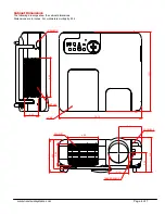
Page 4: ...gs show the cabinet dimensions Dimensions are in inches For millimeters multiply by 25 4 www necvisualsystems com Page 4 of 7 3 63 13 14 12 71 4 53 5 14 5 48 3 09 LAMP INTAKE 6 28 IMAGE SENSOR 3 49 4 92 EXHAUST 2 21 IR SENSOR IR SENSOR 3 19 ...

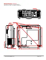
Page 5: ...rawings show the cabinet dimensions Dimensions are in inches For millimeters multiply by 25 4 3 39 MAX M4x8 FOR MOUNT 10 63 9 49 10 27 0 35 0 67 0 47 9 92 IR SENSOR 3 50 2 38 INTAKE AIR FILTER INTAKE IR SENSOR www necvisualsystems com Page 5 of 7 ...

Page 6: ...g Mount Dimensions Model MT60CM The following drawings show ceiling mount dimensions Dimensions are in inches For millimeters multiply by 25 4 www necvisualsystems com Page 6 of 7 11 00 11 50 2 07 5 75 3 75 3 66 5 45 ...

Page 7: ...5H 18H 00H 00H 00H 00H 30H Letterbox 03H 10H 00H 00H 05H 18H 00H 00H 01H 00H 31H Widescreen 03H 10H 00H 00H 05H 18H 00H 00H 02H 00H 32H 4 3 Fill 03H 10H 00H 00H 05H 18H 00H 00H 04H 00H 34H AUTO ADJUST 02H 0FH 00H 00H 02H DDH 00H F0H NOTE Contact your NEC rep for codes not listed Cable Connection Communication Protocol PC Control Connector D Sub 9P Baud Rate 38400 bps Data Length 8 bits Parity No P...

Reviews: