background image

English-4

Contents

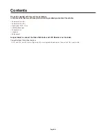
The parts supplied with this unit are as follows.
In the rare case that one of these parts is missing or damaged, contact the retailer.

•  Power cord (1.8 m US)
•  Power cord (1.8 m EU)
•  Signal cable (DVI-D, 1.8 m)
•  USB/RS-485 adapter
•  LAN cable (3 m)
•  Utility disk
•  Setup manual

A signal cable to connect the Video Distributor and LED Module is not included.

Compatible Signal Cable Specifications

- DVI-D dual link (max 30 meters: Signal quality may degrade depending on the quality of the signal cable)

Summary of Contents for LED-VD1

Page 1: ...User s Manual Video Distributor LED VD1 ...

Page 2: ... 5 Rear panel English 5 Connections English 6 Connecting an External Device English 6 Connecting the Power English 6 Connection Methods English 7 Installing Drivers English 8 Troubleshooting English 10 Appendix English 11 Specifications English 11 Pin Assignment RS 485 English 11 Communications Protocol English 11 Dimensional Drawing English 12 Manufacturer s Recycling and Energy Information Engli...

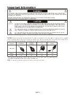
Page 3: ...ce with the instruction manual may cause harmful interference to radio communications Operation of this equipment in a residential area is likely to cause harmful interference in which case the user will be required to correct the interference at his own expense If necessary the user should contact the dealer or an experienced radio television technician for additional suggestions The user may fin...

Page 4: ...angerous to make any kind of contact with any part inside this unit This symbol alerts the user that important literature concerning the operation and maintenance of this unit has been included Therefore it should be read carefully in order to avoid any problems CAUTION Please use the power cord provided with this display in accordance with the table below If a power cord is not supplied with this...

Page 5: ...ted openings or place the video distributor near a radiator or other heat sources Do not put anything on top of the video distributor The power cable connector is the primary means of detaching the system from the power supply The video distributor should be installed close to a power outlet which is easily accessible Do not move or mount this product by hanging a rope or wire to the backside hand...

Page 6: ...iler Power cord 1 8 m US Power cord 1 8 m EU Signal cable DVI D 1 8 m USB RS 485 adapter LAN cable 3 m Utility disk Setup manual A signal cable to connect the Video Distributor and LED Module is not included Compatible Signal Cable Specifications DVI D dual link max 30 meters Signal quality may degrade depending on the quality of the signal cable ...

Page 7: ...here 2 Power Switch Turns ON or OFF the power This device has no standby function 3 Cooling Fan Vent Vent for the cooling fan Do not cover the ventilation 4 DVI Input The DVI input terminal Connect a digital output device here 5 DVI Output The DVI output terminal This is used when connecting this device in a cascaded connection 6 DVI Output for LED Module DVI output for the LED module Connect to t...

Page 8: ... than the indicated voltage Doing so may cause a fire or electric shock Use a power cord appropriate for your region if the power cord included is not compatible with your region If the power cord has a ground wire always be sure to ground it When disconnecting the ground be sure to disconnect the power plug from the outlet before removing the ground Also make sure that the ground wire of the powe...

Page 9: ...fore connecting to the device turn off the power to the device you are connecting to and all peripheral devices Refer to the user s manuals for those devices Video processor LED VP1 Computer USB RS485 adapter LED module LED 06AF1 LED 15BF1 LED module ...

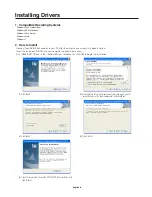
Page 10: ...ve successfully been installed Insert the included CD ROM into your computer s optical media drive Run RS485_SETUP exe in the Software Driver folder on the CD ROM to begin the installation 1 Click Next 2 View the terms of the license agreement and if you agree select I accept the terms of the license agreement and click Next 3 Click Next 4 Click Install 5 Check the box beside Launch the CP210x VCP...

Page 11: ...English 9 6 Click Install 7 The Success window will be displayed OK Click to complete the driver installation ...

Page 12: ...d 5th pins of the RJ 45 cable are used for communication Check to ensure that the 4th and 5th pins of your LAN cable are connected properly Be sure to only use a straight type LAN cable Check to ensure that you are not using a crossover LAN cable No image signal is displayed The image signal is only compatible with 1024x768 60Hz Check the resolution of the input signal The DVI Input Light is flash...

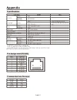
Page 13: ...nvironment Temperature 20 C to 40 C Humidity 10 to 90 without condensation Storage Environment Temperature 30 C to 60 C Humidity 10 to 90 without condensation 1 Up to 8 LED VD1s can be connected in a cascaded connection 2 Up to 25 LED modules can be connected in a cascaded connection 3 Include USB RS 485 adapter Use any commercially available LAN cable category 5 straight type maximum 100 m in len...

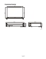
Page 14: ...English 12 Dimensional Drawing 479 2 90 98 2 86 1 10 3 325 1 407 280 290 5 Unit mm ...

Page 15: ... the end of its life All required information concerning the disposal of the product and country specific information on recycling facilities can be found on our following websites http www nec display solutions com greencompany in Europe http www nec display com in Japan or http www necdisplay com in USA WEEE Mark European Directive 2002 96 EC Within the European Union EU wide legislation as impl...

Reviews: