background image

English-21

English

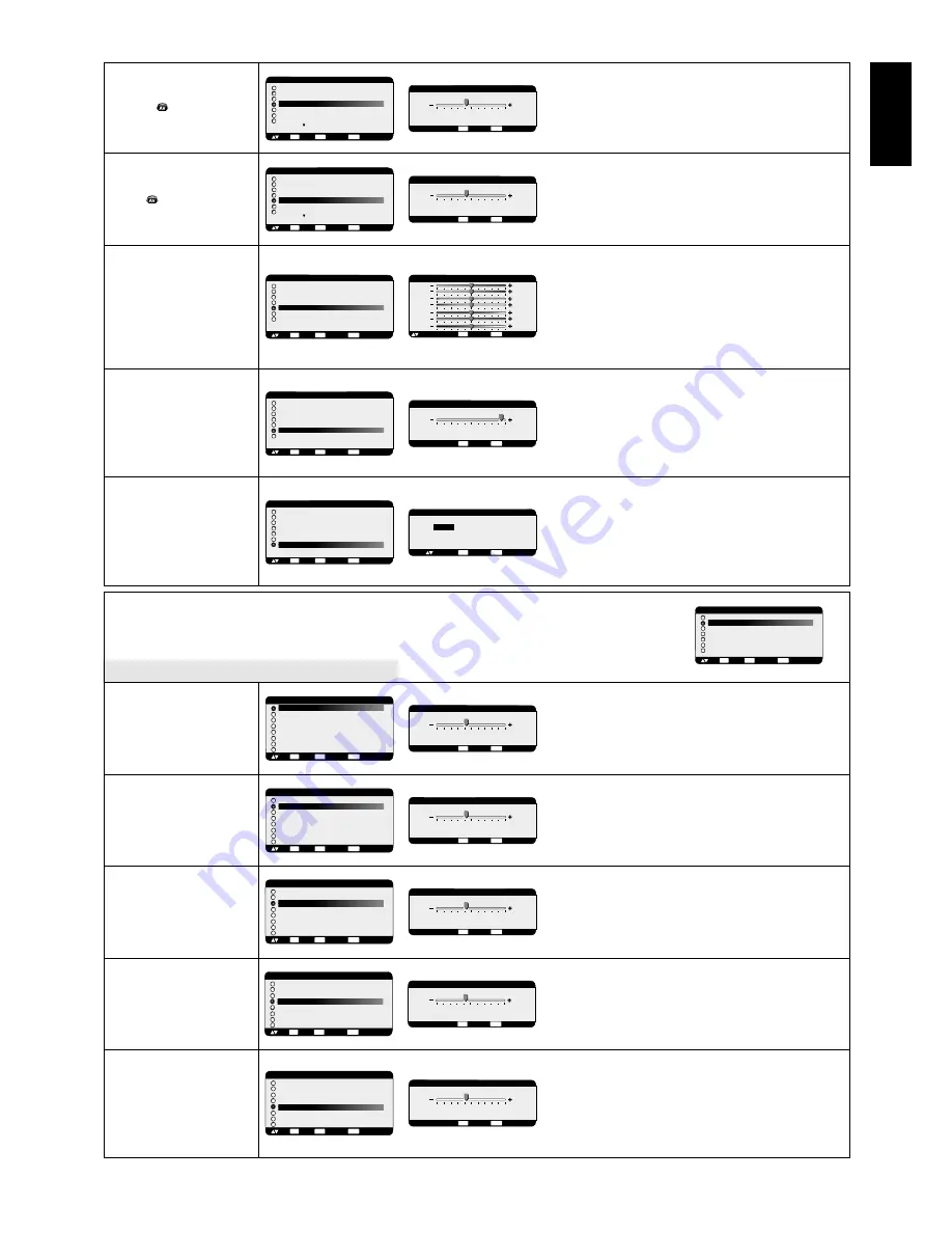
Adjust the tint of the screen.

Press + button to make flesh tone become greenish.
Press - button to make flesh tone becomes purplish.

Adjust the colour depth of the screen.

Press + button to increase colour depth.
Press - button to decrease colour depth.

R, Y, G, C, B, M, S: Increases or decreases Red, Yellow,
Green, Cyan, Blue, Magenta and Saturation depending
upon which is selected. The change in colour will appear
on screen and the direction (increase or decrease) will be
shown by the colour bars.
NOTE: sRGB picture mode is standard and cannot be
changed.

Adjusts the colour temperature of entire screen.
A lower colour temperature makes the screen reddish
and a higher colour temperature makes the screen
bluish.
NOTE: sRGB picture mode is standard and cannot be
changed.

Selecting Picture reset allows you to reset all OSM
settings within the PICTURE menu.
Select “Yes” and press “SET” button to restore to factory
preset data.
Press “EXIT” button to cancel and then return to the
previous menu.

 TINT

*:INPUT DVD/HD, VIDEO only

 COLOR

*:INPUT DVD/HD, VIDEO only

COLOR CONTROL

*:INPUT RGB1,2,3 only

COLOR

TEMPERATURE

PICTURE RESET

PICTURE

BRIGHTNESS
CONTRAST
SHARPNESS
BLACK LEVEL
COLOR CONTROL
COLOR TEMPERATURE

PICTURE RESET

:SEL

SET

:NEXT

:RETURN

MENU

:EXIT MENU

EXIT

PICTURE RESET

:RETURN

MENU

:EXIT MENU

NO

YES

:SEL

EXIT

PICTURE

BRIGHTNESS
CONTRAST
SHARPNESS
BLACK LEVEL
COLOR CONTROL

COLOR TEMPERATURE

PICTURE RESET

:SEL

SET

:NEXT

:RETURN

MENU

:EXIT MENU

EXIT

+ -:ADJ

:RETURN

MENU

:EXIT MENU

9600K

COLOR TEMPERATURE

EXIT

PICTURE

BRIGHTNESS
CONTRAST
SHARPNESS
BLACK LEVEL

COLOR CONTROL

COLOR TEMPERATURE
PICTURE RESET

:SEL

SET

:NEXT

:RETURN

MENU

:EXIT MENU

EXIT

+ -:ADJ

:RETURN

MENU

:EXIT MENU

COLOR CONTROL

R
Y
G
C
B
M
S

0
0
0
0
0
0
0

EXIT

:SEL

PICTURE

BRIGHTNESS
CONTRAST
SHARPNESS
TINT

COLOR 

BLACK LEVEL
NOISE REDUCTION

:SEL

SET

:NEXT

:RETURN

MENU

:EXIT MENU

EXIT

+ -:ADJ

:RETURN

MENU

:EXIT MENU

32

COLOR

EXIT

PICTURE

BRIGHTNESS
CONTRAST
SHARPNESS

TINT

COLOR 
BLACK LEVEL
NOISE REDUCTION

:SEL

SET

:NEXT

:RETURN

MENU

:EXIT MENU

EXIT

+ -:ADJ

:RETURN

MENU

:EXIT MENU

32

TINT

EXIT

Main-Menu

SCREEN

Sub-Menu

Controls Horizontal Image position within the display
area of the LCD.

Press + button to move screen to right.
Press - button to move screen to left.

Controls Vertical Image position within the display
area of the LCD.

Press + button to move screen to UP.
Press - button to move screen to DOWN.

Press + button to expand the width of the image on
the screen to the right.
Press - button to narrow the width of the image on the
screen to the left.

Adjusts image noise (snow).

Adjusts the horizontal size by increasing or decreasing
this setting.
Press + button to expand the width of the image on
the screen.
Press - button to narrow the width of the image on
the screen.

H POSITION

V POSITION

CLOCK

*:INPUT RGB2/3 only

CLOCK PHASE

*:INPUT RGB2/3 only

H RESOLUTION

*:INPUT RGB1/2/3 only

MAIN MENU

PICTURE

SCREEN

AUDIO
PIP
CONFIGURATION 1
CONFIGURATION 2
ADVANCED OPTION

:SEL

SET

:NEXT

:RETURN

MENU

:EXIT MENU

EXIT

SCREEN

H POSITION
V POSITION
CLOCK
CLOCK PHASE

H RESOLUTION

V RESOLUTION
ZOOM MODE
SCREEN RESET

:SEL

SET

:NEXT

:RETURN

MENU

:EXIT MENU

EXIT

+ -:ADJ

:RETURN

MENU

:EXIT MENU

1360

H RESOLUTION

EXIT

SCREEN

H POSITION
V POSITION
CLOCK

CLOCK PHASE

H RESOLUTION
V RESOLUTION
ZOOM MODE
SCREEN RESET

:SEL

SET

:NEXT

:RETURN

MENU

:EXIT MENU

EXIT

+ -:ADJ

:RETURN

MENU

:EXIT MENU

18

CLOCK PHASE

EXIT

SCREEN

H POSITION
V POSITION

CLOCK

CLOCK PHASE
H RESOLUTION
V RESOLUTION
ZOOM MODE
SCREEN RESET

:SEL

SET

:NEXT

:RETURN

MENU

:EXIT MENU

EXIT

+ -:ADJ

:RETURN

MENU

:EXIT MENU

1782

CLOCK

EXIT

SCREEN

H POSITION

V POSITION

CLOCK
CLOCK PHASE
H RESOLUTION
V RESOLUTION
ZOOM MODE
SCREEN RESET

:SEL

SET

:NEXT

:RETURN

MENU

:EXIT MENU

EXIT

+ -:ADJ

:RETURN

MENU

:EXIT MENU

0

V POSITION

EXIT

+ -:ADJ

:RETURN

MENU

:EXIT MENU

0

H POSITION

EXIT

SCREEN

H POSITION

V POSITION
CLOCK
CLOCK PHASE
H RESOLUTION
V RESOLUTION
ZOOM MODE
SCREEN RESET

:SEL

SET

:NEXT

:RETURN

MENU

:EXIT MENU

EXIT

Summary of Contents for LCD5710-2-IT - MultiSync - 57" LCD Flat Panel...

Page 1: ...User s Manual MultiSync LCD5710 57 LCD Colour Monitor...

Page 2: ...al Interface Equipment English 15 Connect the LCD Monitor to a Computer with a Digital Output English 15 Connecting a DVD Player with component out English 16 Connect the LCD Monitor to a DVD Player E...

Page 3: ...ower cord or equivalent to ensure FCC compliance 2 Please use the supplied shielded video signal cable 15 pin mini D SUB to 15 pin mini D SUB 3 Please attach the ferrite cores on the Audio Cable Pleas...

Page 4: ...yo 108 0023 Japan CAUTION Please use the power cord provided with this display in accordance with the table below If a power cord is not supplied with this equipment please contact your supplier For a...

Page 5: ...r cable connector is the primary means of detaching the system from the power supply The monitor should be installed close to a power outlet which is easily accessible Handle with care when transporti...

Page 6: ...2 Ferrite Core x 2 Speaker Plug x 1set Required for optional Loudspeakers Stand 1 x 2 Thumbscrew for stand x 2 Main switch cover CD ROM Ferrite Core x 2 Band x 2 Thumbscrew for stand x 2 Stand 1 x 2 S...

Page 7: ...more than 3 seconds To resume back to user mode press both of and and hold simultaneously for more than 3 seconds 1 POWER button Switches the power on off See page 18 2 MUTE button Switches the audio...

Page 8: ...KER TERMINAL To output the audio signal from AUDIO 1 2 or 3 jack 1 AC IN connector Connects with the supplied power cord 2 RGB 1 IN DVI D To input digital RGB signals from a computer or HDTV device ha...

Page 9: ...not support 1080i input signals If a 1080i signal is used for PIP then the sub picture on the screen will be blank The PIP function will work with 1080p signals 10 STILL button ON OFF button To switc...

Page 10: ...10 ft Operating Range for the Remote Control Caution The remote control system may not function when direct sunlight or strong illumination strikes the remote control sensor of the LCD monitor or when...

Page 11: ...e and indications inside the case 3 Replace the cover CAUTION Incorrect use of batteries can result in leaks or bursting Be careful especially about the following points Place AA size batteries matchi...

Page 12: ...screws with a screwdriver or with your fingers and place them in a safe place for reuse CAUTION Handle with care when mounting the display stand and avoid pinching your fingers NOTE Place stand onto m...

Page 13: ...ays 1 In the upright position How to Mount and Attach Options to the LCD Monitor 2 Lay the screen face down Lay the protective sheet which was wrapped around the monitor when it was packaged on a tabl...

Page 14: ...io Cable For PC Audio Cable Ferrite Core Connections Before making connections First turn off the power of all the external equipment and then make the necessary connections Refer to the user manual i...

Page 15: ...uded Select RGB 3 from the INPUT button When connecting one or more LCD monitors use the RGB OUT connector BNC The AUDIO IN 1 2 and 3 can be used for audio input For connection select AUDIO 1 2 or 3 f...

Page 16: ...owerBook set Mirroring to Off Refer to your Macintosh s owner s manual for more information about your computer s video output requirements and any special identification or configuring your monitor s...

Page 17: ...he RGB 1 IN connector also accepts a DVI D cable Input TMDS signals conforming to DVI standards To maintain display quality use a cable with a quality prescribed by DVI standards The AUDIO IN 1 2 and...

Page 18: ...rs such as DVI D connector Select DVI HD mode from the DVI MODE menu when you connect a DVI D connector Mode selection see DVI MODE of page 25 The AUDIO IN 2 and 3 both RCA can be used for audio input...

Page 19: ...on the amplifier Do not reverse the audio left and right jacks The AUDIO IN is used for audio input The AUDIO OUT jack outputs sound from the selected Audio input Connecting to a Stereo Amplifier LCD...

Page 20: ...e Main Power Switch on the LCD monitor Main Power Switch Power Button 2 Using the remote control Note Before operating the remote control be sure to turn on the Main Power Switch on the LCD monitor 3...

Page 21: ...n OSM Video Input mode Input signal Information Audio input mode Picture Size mode RGB2 1024 x 768 48kHz 60Hz AUDIO 1 SIZE FULL Video Input mode Audio input mode Picture Size mode DVD HD AUDIO 3 SIZE...

Page 22: ...dependently for each picture mode Press button to increase sharpness Press button to decrease sharpness Adjusts the image brightness in relation to the background Press button to increase black level...

Page 23: ...NU EXIT ADJ RETURN MENU EXIT MENU 32 COLOR EXIT PICTURE BRIGHTNESS CONTRAST SHARPNESS TINT COLOR BLACK LEVEL NOISE REDUCTION SEL SET NEXT RETURN MENU EXIT MENU EXIT ADJ RETURN MENU EXIT MENU 32 TINT E...

Page 24: ...X 1 00 0 0 ZOOM H ZOOM V ZOOM H POS V POS EXIT ZOOM MODE CUSTOMV 16 9 14 9 DYNAMIC OFF SEL SET NEXT RETURN MENU EXIT MENU EXIT SCREEN H POSITION V POSITION CLOCK CLOCK PHASE H RESOLUTION V RESOLUTION...

Page 25: ...e auto brightness ON OFF When ON is selected the brightness will be automatically adjusted When RGB ON is selected the monitor will go to power management mode when RGB1 2 3 sync is lost When VIDEO ON...

Page 26: ...turn the previous menu SCREEN SAVER COLOR SYSTEM INPUT VIDEO only SIDE BORDER COLOR CONFIGURATION RESET FACTORY RESET CONFIGURATION 1 POWER SAVE LANGUAGE SCREEN SAVER COLOR SYSTEM SIDE BORDER COLOR CO...

Page 27: ...en Press button to move to the left side of the screen Press button to move to the top of the screen Press button to move to the bottom of the screen CONFIGURATION 2 LONG CABLE ON OFF LONG CABLE MANUA...

Page 28: ...RETURN MENU EXIT MENU MONITOR INFORMATION MODEL NAME LCD5710 SERIAL 12315XXX EXIT Main Menu ADVANCED OPTION Sub Menu Selects the S Video input port function PRIORITY If cable is connected to the S Vi...

Page 29: ...mber of horizontal displays V MONITORS Selects the number of vertical displays POSITION Selects a position to expand the screen TILE COMP Works in tandem with TILE MATRIX to compensate for the width o...

Page 30: ...h all personal display devices NEC DISPLAY SOLUTIONS recommends displaying moving images and using a moving screen saver at regular intervals whenever the screen is idle or turning off the monitor whe...

Page 31: ...o 4 Operate wireless remote controller while aiming at the PRIMARY monitor The MENU OSM will appear on the selected ID No s monitor NOTE If ID No select OSM is showing at the PRIMARY monitor press DIS...

Page 32: ...trol_LCD5X10 pdf When using the following control commands all of the daisy chained monitors can be controlled at the same time from one monitor Reply and status commands however will only pertain to...

Page 33: ...uter ask Power status of monitor the status of monitor is powered on Command from computer Command from Monitor Detail of command 30 30 76 50 0D 0 0 v P enter Ask about the power status of monitor 30...

Page 34: ...atically optimizing display performance IPM Intelligent Power Manager System Provides innovative power saving methods that allow the monitor to shift to a lower power consumption level when on but not...

Page 35: ...al timings If your text is garbled change the video mode to non interlace and use 60Hz refresh rate Image of component signal is greenish Check to see if the DVD HD input connector is selected LED on...

Page 36: ...put RCA PIN JACK L R 1 Output 0 15Vrms with 1k ohm terminated Speaker Output External Speaker Jack 7W 7W 8 ohm Resolutions Supported 640 x 480 at 60Hz to 85Hz 800 x 600 at 50Hz 60Hz to 85Hz 1024 x 768...

Page 37: ...and the LED indicator light is on the bottom This will allow for proper ventilation and will extend the lifetime of the monitor Improper ventilation may shorten the lifetime of the monitor Mounting lo...

Page 38: ...C Chroma 3 Digital RGB input DVI D R G B 1 4 RS 232C input output Pin No Name 1 NC 2 RXD 3 TXD 4 NC 5 GND 6 NC 7 RTS 8 CTS 9 NC Pin Assignment of DVI connector 1 TX2 9 TX1 17 TX0 2 TX2 10 TX1 18 TX0 3...

Reviews: