


User’s Manual U16622EJ1V0UM
24
CHAPTER 4 CAUTIONS
The following must be observed when using the IE-703204-G1-EM1.
4.1
Connection with Target System
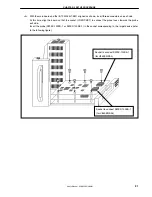
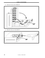
Turn off power to the IE-V850ES-G1 before connecting the IE-703204-G1-EM1 to the target system.
4.2
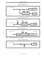
Characteristics of Target Interface
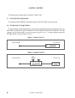
The target interface (signals connecting the in-circuit emulator and the target system) functionally operates as if an
actual device is connected, however, the characteristics may be different than those of the actual device. The target
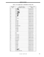
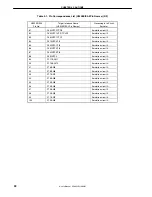
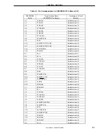
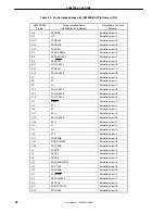
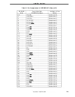
interface of the IE-703204-G1-EM1 is one of those shown in Figures 4-1 to 4-12. The target interface processing of
each target device is shown in Tables 4-1 and 4-2.
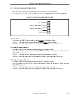
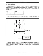
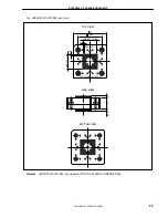
Figure 4-1. Equivalent Circuit A
PD70F3204Y
Emulation CPU
Port
pin
Target system side
IE system side
µ
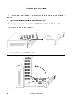
Figure 4-2. Equivalent Circuit B
EP1K100FC484
(FPGA)
P174AVC16245
(Voltage level shifter)
A
B
3.6 V
Same
potential
as V
DD
Target system side
IE system side
VCCB
VCCA


