


8
8
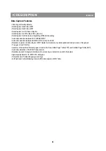
Data Capture
¥ Text memory 10 pages
¥ Inventory of transmitted Teletext pages stored in the Transmitted Page Table (TPT) and Subtitle Page Table (SPT)
¥ Data Capture for 525/625 line WST, VPS (PDC system A) and Wide Screen Signalling (WSS) bit decoding Automatic
selection between 525 WST/625 WST
¥ Automatic selection between 625 WST/VPS on line 16 of VBI
¥ Real-time capture and decoding for WST Teletext in Hardware, to enable optimised -processor throughput
¥ Automatic detection of FASTEXT transmission
¥ Real-time packet 26 engine in Hardware for processing accented, G2 and G3 characters
¥ Signal quality detector for video and WST/VPS data types
¥ Comprehensive teletext language coverage
¥ Full Field and Vertical Blanking lnterval (VBI) data capture of WST data
Display
¥ Teletext and Enhanced OSD modes
¥ Features of lever 1.5 WST.
¥ Serial and Parallel Display Attributes
¥ Single/Double/Quadruple Width and Height for characters
¥ Scrolling of display region
¥ Variable flash rate controlled by software
¥ Enhanced display features including overlining, underlining and italics
¥ Soft colours using CLUT with 4096 colour palette
¥ Globally selectable scan lines per row (9/10/13/16) and character matrix [12x10, 12xl3, 12x16 (VxH)]
¥ Fringing (Shadow) selectable from N-S-E-W direction
¥ Fringe colour selectable
¥ Meshing of defined area
¥ Contrast reduction of defined area
¥ Cursor
¥ Special Graphics Characters with two planes, allowing four colours per character
¥ 32 software redefinable On-Screen display characters
¥ 4 WST Character sets (GO/G2) in single device (e.g. Latin, Cyrillic, Greek, Arabic)
¥ G1 Mosaic graphics, Limited G3 Line drawing characters
¥ WST Character sets and Closed Caption Character set in single device
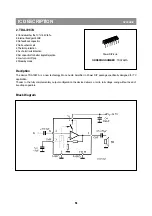
Data Capture
The Data Capture section takes in the analogue Composite Video and Blanking Signal (CVBS), and from this extracts the
required data, which is then decoded and stored in memory.
The extraction of the data is performed in the digital domain. The first stage is to convert the analogue CVBS signal into a
digital form. This is done using an ADC sampling at 12MHz. The data and clock recovery is then performed by a Multi-
Rate Video Input Processor (MuIVIP). From the recovered data and clock the following data types are extracted WST
Teletext (625/525), Closed Caption, VPS, WSS. The extracted data is stored in either memory (DRAM) via the Memory
Interface or in SFR locations.
8
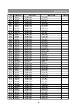
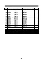
IC DESCRIPTION
APPENDIX
Summary of Contents for DTA-14V4THS
Page 4: ...3 CIRCUIT BLOCK DIAGRAM ISO1 S W IC ISO2 S W IC Monitor Out Audio Monitor Out Video I602 I702...
Page 7: ...6...
Page 8: ...7 7 EXPLODED VIEW 1 14V4 20v4 21v4...
Page 9: ...8 PCB MAIN CP 185A...
Page 31: ...10 10 10 IC DESCRIPTION APPENDIX...
Page 34: ...13 13 13 IC DESCRIPTION APPENDIX TDA 9361 OR TDA9381...
Page 38: ...17 17 3 STV9302A 17 IC DESCRIPTION APPENDIX fi...
Page 39: ...18 18 IC DESCRIPTION APPENDIX...
Page 40: ...19 19 IC DESCRIPTION APPENDIX...
Page 41: ...20 20 IC DESCRIPTION APPENDIX...
Page 42: ...21 21 IC DESCRIPTION APPENDIX...
Page 43: ...22 22 IC DESCRIPTION APPENDIX...
Page 44: ...23 23 IC DESCRIPTION APPENDIX...
Page 45: ...24 IC DESCRIPTION APPENDIX...
Page 46: ...25 IC DESCRIPTION APPENDIX...
Page 47: ...26 IC DESCRIPTION APPENDIX...
Page 48: ...27 IC DESCRIPTION APPENDIX...
Page 49: ...28 IC DESCRIPTION APPENDIX...
Page 50: ...29 IC DESCRIPTION APPENDIX...
Page 51: ...30 IC DESCRIPTION APPENDIX...
Page 52: ...31 IC DESCRIPTION APPENDIX...
Page 55: ......