


2
2
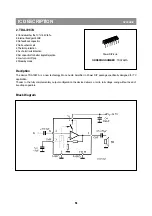
The vertical synchronisation is realised by means of a divider circuit. The vertical ramp generator needs an external
resistor and capacitor. For the vertical drive a differential output current is available. The outputs are DC coupled to the
vertical output stage.
The following geometry parameters can be adjusted:
¥ Horizontal shift
¥ Vertical amplitude
¥ Vertical slope
¥ S-correction
¥ Vertical shift
Chroma and luminance processing
The chroma band-pass and trap circuits (including the SECAM cloche filter) are realised by means of gyrators and are
tuned to the right frequency by comparing the tuning frequency with the reference frequency of the colour decoder. The
luminance delay line and the delay cells for the peaking circuit are also realised with gyrators. The circuit contains a black
stretcher functi on which corrects the black level for incoming signals which have a difference between the black level and
the blanking level.
Colour decoder
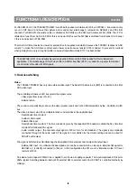
The ICs can decode PAL, NTSC and SECAM signals. The PAL/NTSC decoder does not need external reference
crystals but has an internal clock generator which is stabilised to the required frequency by using the 12 MHz clock signal
from the referenc oscillator of the -Controller/Teletext decoder.
The Automatic Colour Limiting (ACL) circuit (switchable via the ACL bit in subaddress 2OH) prevents oversaturation
occurring when signals with a high chroma-to-burst ratio are received. The ACL circuit is designed such that it only
reduces the chroma signal and not the burst signal. This has the advantage that the colour sensitivity is not affected by
this function.
SOFTWARE CONTROL
The CPU communicates with the peripheral functions using Special function Registers (SFRS) which are addressed as
RAM locations. The registers for the Teletext decoder appear as normal SFRs in the -Controller memory map and are
written to these functions by using a serial bus. This bus is controlled by dedicated hardware which uses a simple
handshake system for software synchronisation.
For compatibility reasons and possible re-use of software blocks, the TV processor is controlled by I2C bus. The TV
processor control registers cannot be read. Only the status registers can be read ( Read address 8A ).
The SECAM decoder contains an auto-calibrating PLL demodulator which has two references, via the divided 12 MHz
reference frequency (obtained from the -Controller) which is used to tune the PLL to the desired free-running frequency
and the bandgap reference to obtain the correct absolute value of the output signal. The VCO of the PLL is calibrated
during each vertical blanking period, when the IC is in search or SECAM mode.
The base-band delay line (TDA 4665 function) is integrated. This delay line is also active during NTSC reception, to
obtain a good suppression of cross colour effects. The demodulated colour difference signals are internally supplied to
the delay line.
2
FUNCTIONAL DESCRIPTION
APPENDIX
Summary of Contents for DTA-14V4THS
Page 4: ...3 CIRCUIT BLOCK DIAGRAM ISO1 S W IC ISO2 S W IC Monitor Out Audio Monitor Out Video I602 I702...
Page 7: ...6...
Page 8: ...7 7 EXPLODED VIEW 1 14V4 20v4 21v4...
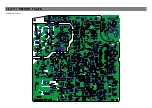
Page 9: ...8 PCB MAIN CP 185A...
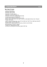
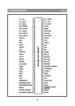
Page 31: ...10 10 10 IC DESCRIPTION APPENDIX...
Page 34: ...13 13 13 IC DESCRIPTION APPENDIX TDA 9361 OR TDA9381...
Page 38: ...17 17 3 STV9302A 17 IC DESCRIPTION APPENDIX fi...
Page 39: ...18 18 IC DESCRIPTION APPENDIX...
Page 40: ...19 19 IC DESCRIPTION APPENDIX...
Page 41: ...20 20 IC DESCRIPTION APPENDIX...
Page 42: ...21 21 IC DESCRIPTION APPENDIX...
Page 43: ...22 22 IC DESCRIPTION APPENDIX...
Page 44: ...23 23 IC DESCRIPTION APPENDIX...
Page 45: ...24 IC DESCRIPTION APPENDIX...
Page 46: ...25 IC DESCRIPTION APPENDIX...
Page 47: ...26 IC DESCRIPTION APPENDIX...
Page 48: ...27 IC DESCRIPTION APPENDIX...
Page 49: ...28 IC DESCRIPTION APPENDIX...
Page 50: ...29 IC DESCRIPTION APPENDIX...
Page 51: ...30 IC DESCRIPTION APPENDIX...
Page 52: ...31 IC DESCRIPTION APPENDIX...
Page 55: ......