background image

Powering Up the System

48

Installation

DSX-80/160 Hardware Manual

Powering Up the System

Before Powering Up

The system’s built-in Automatic Slot Con

fi

guration automatically sets up station and line cards when you 

initially power up the system. On power up, the system scans the cards from left to right and sets up the sta-
tion and line numbering as follows:

Extension numbers will begin with 300 in the 

fi

rst slot and increment from left to right.

Line numbers will begin with 101 (starting from the 

fi

rst installed COIU or T1/E1/PRI Card) and will 

also increment from left to right.

For example, in a 16x32, the numbering will be:

1st 16ESIU Card = Extensions 300-315.
2nd 16ESIU Card = Extensions 316-331.
16COIU Card = Lines 101-116.

In addition, the system will also automatically set up a station or line card when you plug it in hot.

To power up the system:

- You do not need to reattach the right side panel before powering up the system. Leaving the right 

side panel removed makes the station and line cabling more accessible.

1.

Make sure the system is properly grounded and the card bracket is reinstalled and secured.

2.

Install a surge protector in the AC outlet you intend to use for system power.

3.

Plug the main cabinet’s AC power cord into its surge protector.

4.

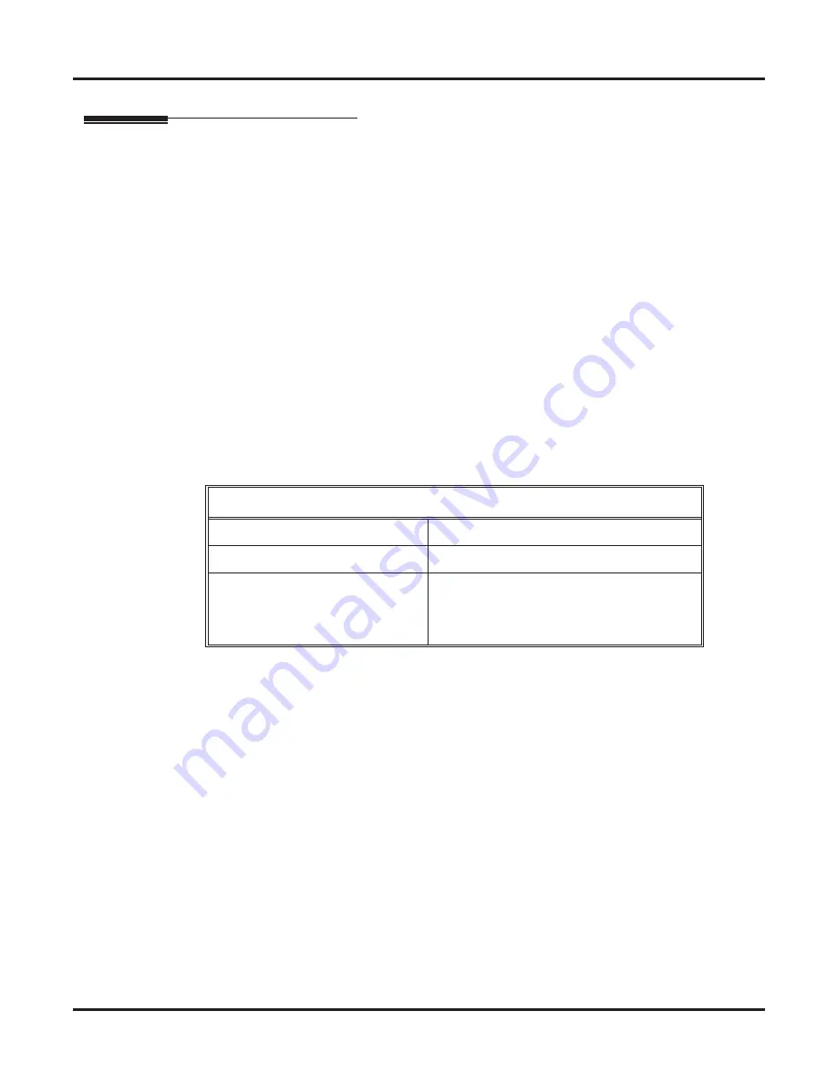
Turn on the main cabinet power switch. After about 30 seconds, verify the system LEDs.

LED

Normal Power-On Status

Power Supply

All three LEDs on (green)

CPU Card

Top LED winks on (blue)

ESIU, SLIU, and COIU Cards

Top LED 

fl

ashing (slowly green)

Bottom LED 

fl

ashes (yellow) when ports 

on the card are busy. The faster the 

fl

ash, 

the more ports are busy.

Summary of Contents for DSX-160

Page 1: ...nents Installation Specifications and Parts DSX 80 160 Hardware Manual P N 1093096 Rev 2 June 2006 Printed in U S A 01 00 00 Empowered by Innovation Upgrading from DS2000 to DSX 80 160 If upgrading fr...

Page 2: ...Solutions Inc has no obligation to provide any updates or corrections to this manual Further NEC Unified Solutions Inc also reserves the right without prior notice to make changes in equipment design...

Page 3: ...eadsets for DSX Cordless Lite II Telephone 8 DESI Telephone Label System 9 DESI Labeling Software 9 DESI Telephone Labels 9 DSX 80 160 Common Equipment 11 DSX 80 4 Slot KSU 11 DSX 160 8 Slot KSU 11 DS...

Page 4: ...nalog Station Cards 33 Connecting 16SLIU and 8SLIU Cards 34 Installing 16COIU and 8COIU Analog Line Cards 35 Connecting 16COIU and 8COIU Cards 36 Installing T1 E1 PRI Cards 37 Connecting the T1 E1 PRI...

Page 5: ...d Relays 59 Mounting the 2PGDAD Module and Connecting to the System 60 External Paging 61 Installing External Paging 61 Music Source 62 Installing a Music Source 62 Power Failure Telephone 63 Power Fa...

Page 6: ...Table of Contents iv Table of Contents DSX 80 160 Hardware Manual...

Page 7: ...4 Interactive Soft Keys for intuitive feature access It also provides 10 Personal Speed Dial bin keys 24 pro grammable Feature Keys and 12 fixed function keys for streamlined operation Additionally th...

Page 8: ...e features include dual LEDs a Ring Message Lamp to show ringing Caller ID and voice mail messages built in wall mounting and an innovative two position angle adjustment 60 Button DSS Console The 60 B...

Page 9: ...in wall mounting and a bridged data jack for connecting a modem or answering machine are standard DTR 1HM 1 Single Line Telephone The DTR 1HM 1 provides all the features of the DTR 1 1 in addition to...

Page 10: ...and mobility An easy to read 16 character by 2 line LCD display with four status icons vol ume controls a rechargeable Nickel Metal Hydride Battery Pack and a handy belt clip round out the elegant an...

Page 11: ...anceling P81N 750634 Polaris Encore Monaural Over the Head Voice Tube P91 Noise Canceling P91N Polaris Encore Binaural Over the Head Voice Tube P101 760635 Noise Canceling P101N DuoSet Convertible Ove...

Page 12: ...Noise Canceling H101N Freehand Monaural In the Ear Voice Tube H131 Noise Canceling H131N DuoSet Convertible Over the Head On the Ear Voice Tube H141 Noise Canceling H141N DuoPro On the Ear Voice Tube...

Page 13: ...x Binaural Noise Canceling Over the Head GN 2127 ST 2100 SoundTube Monaural Sound Tube On the Ear GN 2127 NC 2100 Flex Monaural Noise Canceling On the Ear 405 SF Surefit Monaural Voice Tube 3 Way Conv...

Page 14: ...are Manual Headsets for DSX Cordless Lite II Telephone The following headsets are available for the DSX Cordless Lite II Telephone M175 Headband Style P N 750637 MX150 Earloop Style P N 750642 At a Gl...

Page 15: ...t Choice of fonts and font colors Space for incorporating company logo User printable background graphics using DESI Preprint DESI labeling software is provided on the DSX System Document CD included...

Page 16: ...System 10 Components DSX 80 160 Hardware Manual For DTR 1HM 1 Black P N 780404 Metallic green P N 780405 Metallic silver P N 780406 Lime green P N 780407 Preprint blank P N 780460 For DTH 1 1 Metalli...

Page 17: ...n the cover for getting essential system status and troubleshooting at a glance DSX 80 160 Power Supply The power supply provides the various DC voltages required to power the DSX 80 160 Cards The DSX...

Page 18: ...8 mono minijacks One audio output for External Paging 1 8 mono minijack Ethernet and USB ports for local and remote PC Programming RS 232 serial port for Station Message Detail Recording Built in V 32...

Page 19: ...Card with HV Message Waiting The 16SLIU Card connects 16 analog extensions which are typically used for single line telephones and fax machines Just like the 16ESIU Card the 16SLIU Card has a Mode Sw...

Page 20: ...n and a port activity LED to indicate traffic on the card See System Configuration page 19 for more Tips to remember The 8SLIU Card provides high voltage message waiting for single line sets with high...

Page 21: ...6 Port CO Line 16COIU Card with Caller ID The 16COIU Card supports 16 analog loop start CO lines The card has a Mode Switch for taking the card out of service a status LED indicating proper card opera...

Page 22: ...two power failure cut through circuits When commercial AC power fails the card automatically cuts through two line circuits to two power failure single line telephones See System Configuration page 19...

Page 23: ...nd routes them quickly and efficiently Integrated Voice Mail features include Conversation Record Answering Machine Emulation and Caller ID with Return Call Interactive Soft Keys guide the display tel...

Page 24: ...s instead Tips to remember The Analog Door Box is a weather tight unit and can be mounted outside The maximum number of DSX Analog Door Boxes you can install is determined by the number of 2PGDAD Modu...

Page 25: ...ard installed in the Qty column The number of keysets single line sets and DSS Consoles does not affect the load factor 2 For each item and for each Load Type multiply the Qty times the Load and enter...

Page 26: ...lled the capacity is If you have two power supplies installed the capacity is If you have three power supplies installed the capacity is 5 VDC 40 5 VDC 80 5 VDC 120 40 VDC 48 40 VDC 80 40 VDC 120 Note...

Page 27: ...gital voltmeter Before Installing Make sure you have a building plan showing the location of the common equipment extensions the telco demarcation and earth ground In addition the installation site mu...

Page 28: ...n Layout DSX 80 below and Figure 2 Installation Layout DSX 160 page 23 for more The Main Equipment Cabinet requires a three prong dedicated 110 VAC 60 Hz circuit NEMA 5 15 recep tacle The AC receptacl...

Page 29: ...the cover 1 Unscrew the two captive screws on the front of the cabinet cover 2 Lift up slightly on the front of the cover then gently slide the cover back to remove it Figure 3 Removing the Cover 15...

Page 30: ...the packing material in the Main Equipment Cabinet box Unpack the wall mount bracket and mounting screws Figure 4 Wall Mount Bracket Mounting the Wall Mount Bracket Mount the wall mount bracket on the...

Page 31: ...wn See Figure 6 Hanging the DSX 80 4 Slot KSU below when hanging a DSX 80 4 Slot KSU See Figure 7 Hanging the DSX 160 8 Slot KSU below when hanging an DSX 160 slot cabinet 2 Using the remaining screws...

Page 32: ...s to the ground lugs and system cabling The cabinet has two ground connections ETH Earth Ground and PBXG PBX Ground To remove the right side panel 1 Remove the two screws that secure the right side pa...

Page 33: ...imp ring terminals as required onto two 12 AWG stranded copper ground wires 3 Install the ring terminals onto the earth and PBX ground terminations and firmly tighten 4 Connect the other end of the gr...

Page 34: ...ual Installing the RFI Suppressor Assembly You must install an RFI Suppressor Assembly for the CPU audio and ethernet cables The suppressor must be mounted inside the cabinet and as close the CPU Card...

Page 35: ...er tighten the two screws that secure the power supply A DSX 160 may require up to 3 power supplies depending on system configuration using slots CN101 CN102 and CN103 Refer to System Preparation page...

Page 36: ...he CPU into slot CN0 Refer to Installing Optional Equipment page 57 when connecting the audio inputs and outputs to the CPU Card Figure 12 Installing the CPU Important Install station equipment connec...

Page 37: ...tall 16ESIU Cards 1 Plug the 16ESIU Card for extensions 300 315 into slot CN1 2 Plug in additional ESIU Cards as required See System Preparation page 21 for more 3 Set the mode switch on each installe...

Page 38: ...WHT WHT ORN ORN WHT WHT GRN GRN WHT WHT BRN BRN WHT WHT SLT SLT WHT RED BLU BLU RED RED ORN ORN RED RED GRN GRN RED RED BRN BRN RED RED SLT SLT RED BLK BLU BLU BLK BLK ORN ORN BLK BLK GRN GRN BLK BLK...

Page 39: ...nalog telephones To install a SLIU Card 1 Turn to System Preparation page 21 to be sure you haven t exceeded the allowable system load factor 2 Plug a SLIU Card into any available slot from CN2 CN8 Yo...

Page 40: ...and 8SLIU Cards 4 Slot Cabinet shown WHT BLU BLU WHT WHT ORN ORN WHT WHT GRN GRN WHT WHT BRN BRN WHT WHT SLT SLT WHT RED BLU BLU RED RED ORN ORN RED RED GRN GRN RED RED BRN BRN RED RED SLT SLT RED BL...

Page 41: ...em Preparation page 21 to be sure you haven t exceeded the allowable system load factor 2 Plug a COIU Card into any available slot from CN2 CN8 You should reserve CN1 for a 16ESIU Card 3 Set the mode...

Page 42: ...order Figure 18 Connecting 16COIU and 8COIU Cards 4 Slot Cabinet shown WHT BLU BLU WHT WHT ORN ORN WHT WHT GRN GRN WHT WHT BRN BRN WHT WHT SLT SLT WHT RED BLU BLU RED RED ORN ORN RED RED GRN GRN RED R...

Page 43: ...32E1 support E1 is not used in North America You can install a T1 E1 PRI Card in any slot except slot 1 A commercially available T1 Tester is recommended Figure 19 Setting Up the T1 E1 PRI Card E1 T1...

Page 44: ...oad factor 2 Set jumpers CN7 and CN9 to the T1 position CN7 and CN9 are not required for T1 installations You can optionally leave them off 3 Plug in T1 E1 PRI Trunk Cards as required 4 Set the mode s...

Page 45: ...generally referred to as a RJ45 connector wired in an RJ61X configuration Check with your local supplier for other compa rable products Suttle SE 266 8K 8 Position Modular Plug requires an SE 166 or S...

Page 46: ...cabinet or facility using the cable shown below Using this same setup you can loop a Tie Line to a DID Line to test your DID routing before connecting to the CSU Figure 23 Making a T1 E1 PRI Crossover...

Page 47: ...iate connectors on the station cards 2 Install a modular jack for each extension within 6 feet of the telephone s location 3 For each extension run one pair 24 AWG station cable from the station block...

Page 48: ...on the right side of the telephone base The line cord does not use a channel and drapes down from the telephone line cord jack or connects to the telephone legs Figure 25 Installing the Handset and L...

Page 49: ...DSS Console connects to an available port on an 16ESIU Card just like a keyset You can install four maximum per system The DSS Console line cord does not use a channel and drapes down from the tele ph...

Page 50: ...Angle Adjustment To set the low viewing angle position 1 Fold the legs all the way back Figure 28 Setting the Low Viewing Angle To set the high viewing angle position 1 Flip up the two leg supports 2...

Page 51: ...stallation Removing the Faceplate You ll need to remove the telephone faceplate to write on the label or install a DESI custom label To remove the faceplate 1 Put your finger in the recessed area unde...

Page 52: ...Connecting Extensions and Setting Up the Telephone 46 Installation DSX 80 160 Hardware Manual To reinstall the faceplate 1 Snap back into place as shown Figure 31 Reinstalling the Telephone Faceplate...

Page 53: ...s page 36 as a guide plug the installation cable mod jacks into the appropriate connectors on the COIU Cards 2 For each line run one pair cross connect wire between the line block and the CPE customer...

Page 54: ...16COIU Card Lines 101 116 In addition the system will also automatically set up a station or line card when you plug it in hot To power up the system You do not need to reattach the right side panel b...

Page 55: ...er present Off 40 V DC power not present 1 0 9 3 0 9 6 2 4 CPU Running blue Off CPU is not functioning On System is starting up Wink On System is running Error red Off No errors present On System has...

Page 56: ...Digital Station ESIU Analog Station SLIU and Analog Line COIU Card LEDs 1093096 25 Sync Status green Fast Flash PCB running waiting for sync Same as having the mode switch set to stop System has an er...

Page 57: ...om the T1 PCB BPV Bi Polar Violation Alarm Red This alarm indicates that consecutive one pulses have been received in the T1 signal in error Off The telco s T1 signal does not contain Bi Polar Violati...

Page 58: ...Installation Reinstalling the Side Panel To reinstall the side panel 1 Carefully realign the right side panel and slide it into position 2 Reattach the two screws that secure the right side panel to t...

Page 59: ...stalling the Front Cover To reinstall the front cover 1 Hook the tabs on the rear of the cover into their associated slots 2 Push the front of the cover into place 3 Screw in the two captive screws th...

Page 60: ...iefly press tap the Reset Switch on the CPU Figure 39 Resetting the System Important If the system s RS 232 connection uses twisted pair cable before resetting do one of the following Make sure the RS...

Page 61: ...erases all your stored programming and returns the system to its default settings 1 Turn off the system 2 Press and hold the Reset Switch on the CPU while turning on the system power 3 When all the LE...

Page 62: ...dvisable backing up the site programming is not required 2 Press and hold the Reset Switch on the CPU 3 When all the LEDs on the CPU light and then go out release the Reset Switch The new system softw...

Page 63: ...hedule and Dial Action Table programing remain intact By default the first 16 300 315 mailboxes are active enabled and the IntraMail Automated Atten dant does not answer outside calls See Start up Int...

Page 64: ...2PGDAD Module has the same environmental requirements as a DSX keyset When choosing a location keep in mind that the front side of the module contains the status LEDs important for troubleshooting wh...

Page 65: ...he wire then release the tab 5 Be sure all module jumpers are in the open position To connect a relay 1 Run one pair 24 AWG station cable from the relay location to the 2PGDAD Module 2 At the relay co...

Page 66: ...lace 3 Program the Door Box and 2PGDAD Module before connecting to the 2PGDAD modular jack In 1203 01 Secondary Station Port Assignment for the 16ESIU port selected enter an available station port for...

Page 67: ...t specifications To connect to an External Paging Amplifier 1 Obtain an audio cable that has a mono audio minijack 1 8 on one end and a connector compatible with the customer s paging amplifier on the...

Page 68: ...ons To connect a music source two maximum 1 Obtain an audio cable that has a mono audio minijack 1 8 on one end and a connector compatible with the customer s music on the other 2 Plug the mono audio...

Page 69: ...ular jack for each Power Failure Telephone within 6 feet of the telephone s location 4 For each Power Failure Telephone run one pair of 24 AWG station cable from the appropriate circuit on the block t...

Page 70: ...ll mounting your DSX telephone you should reverse the handset hanger The hanger holds the handset in place while the telephone is mounted on the wall To reverse the wall mount handset hanger 1 Slide o...

Page 71: ...n 2 Fold the telephone legs into the wall mount position 3 Make sure the handset coil cord is routed through the lower channel in the base 4 Fold the two leg supports down flush with the legs 5 Plug a...

Page 72: ...Leave the heads exposed about 1 4 2 Fold the telephone legs into the wall mount position 3 Make sure the handset coil cord and line cord are routed through the lower channels in the base 4 Fold the tw...

Page 73: ...a standard wall plate in a convenient location 2 Fold the DSS Console legs into the wall mount position 3 Fold the two leg supports down flush with the legs 4 Plug a short line cord into the DSS Cons...

Page 74: ...vertically Leave the heads exposed about 1 4 2 Fold the DSS Console legs into the wall mount position 3 Make sure the line cord is routed through the lower channel in the base 4 Fold the two leg supp...

Page 75: ...Key Name table below Example for Feature Key 4 you see PUSH L 4 To test the key and Ring Message Lamp LEDs 1 Press Volume Up All the keys with lamps light green except for MUTE which doesn t have a gr...

Page 76: ...t port when connecting a PC locally for the System Administrator Use the serial port only for SMDR Adaptor DB9 Female to Mod 6 Jack Figure 54 Connecting a PC to the System 1 0 9 3 0 9 6 4 Standard A B...

Page 77: ...0 Lines 64 Digital Telephones DSX 80 32 DSX 160 96 Analog Telephones DSX 80 48 DSX 160 80 DSS Consoles 4 max per system Plugs into a digital station port Power Failure Telephones 2 per COIU Card Inter...

Page 78: ...aces where shocks or vibrations are frequent or strong 4 In places where water or other fluids come in contact with the main equipment 5 In areas near high frequency machines or electric welders 6 Nea...

Page 79: ...C voltage measured at the MDF between tip and ring On Hook Idle State Minimum 44 VDC On Hook Idle State Maximum 56 VDC Off Hook Active State 7 5 VDC typical depending on the telephone type and loop le...

Page 80: ...set 7 5 8 9 1 2 4 3 4 2 lb 5 7 oz 60 Button DSS Console 5 5 8 9 1 2 4 3 4 1 lb 3 4 oz BGM MOH Music Source Inputs Music inputs are located on the CPU Card Input Impedance 10K Ohms Input Level 18 dBr 2...

Page 81: ...ts 1 Do not run station cable parallel with the AC source telex or computer etc If the cables are near cable runs to those devices use shielded cable with grounded shields or install the cable in cond...

Page 82: ...ck 1090029 White DTH 1 1 Single Line Telephone 780034 DTR 1 1 Single Line Telephone 780020 Black 780021 White DTR 1HM 1 Single Line Telephone 780025 Black 780026 White Analog Door Box 922450 2PGDAD Mo...

Page 83: ...DSX 34 Button Super Display Telephone White 1093082 DSX 34 Button Super Display Telephone Black 1093081 DSX 60 Button DSS White 1093080 DSX 60 Button DSS Black 1093079 DTR 1 1 Telephone Labels Black...

Page 84: ...6 conductor line cord 1091014 Cards Description Part Number CPU Card 1090010 16 Port Digital Station Card 16ESIU 1091004 16 Port Analog Station Card with HV Message Waiting 16SLIU 1091007 8 Port Anal...

Page 85: ...nt Parts Description Part Number Handset and Cord Assembly 1091016 22 Button Clear Plastic Cover 1091018 34 Button Clear Plastic Cover 1091019 34 Button Super Display Clear Plastic Cover 1091020 60 Bu...

Page 86: ...Parts List 80 Specifications and Parts DSX 80 160 Hardware Manual...

Page 87: ...ns com Other Important Telephone Numbers Sales 203 926 5450 Customer Service 203 926 5444 Customer Service FAX 203 926 5454 Technical Service 203 925 8801 Discontinued Product Service 900 990 2541 Tec...

Page 88: ...1093096 June 9 2006 Rev 2 Printed in U S A NEC Unified Solutions Inc 4 Forest Parkway Shelton CT 06484 TEL 203 926 5400 FAX 203 929 0535 www necunifiedsolutions com...

Reviews: