4-2
System Boards
This chapter includes information on the five circuit boards used in the notebook.
Mini PCI Board
The Mini PCI LAN/modem board is located under the top cover assembly. The board is
mounted on the communications board. The Mini PCI board connectors include
communications board cable connector J1, a modem cable connector, and a LAN cable
connector.
Power Switch Board
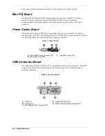
The power switch board (G7EZAB) is located under the top cover assembly. The board is
mounted on the right side of the notebook, between the hard drive bay and the side of the base.
The following figure shows the board and its connectors and ports.
Power switch board
A
– Main Board Cable Connector P51
C
– Headphone Jack P53
B
– Microphone Jack P52
USB Connector Board
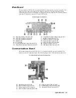
The USB connector board (G7EWK A 2/3) is located under the top cover assembly. The board
is mounted on the left side of the notebook. The following figure shows the board and its
connectors and ports.
USB connector board
A
– USB Port
D
– Cable Connector P42
B
– Parallel Port
E
– Mini PCI Board Cable Connector P43
C
– Main Board Cable Connector P41
Summary of Contents for DayLite Series
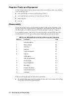
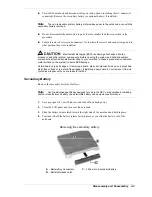
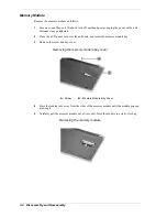
Page 42: ...3 Disassembly and Reassembly Required Tools and Equipment Disassembly Reassembly ...
Page 58: ...5 Illustrated Parts Breakdown Illustrated Parts Breakdown Parts List ...
Page 65: ...7 Troubleshooting Problem Checklist Startup Problems Diagnostics ...
Page 73: ...8 NEC Computers Information Services Service and Support Functions Technical Support ...
Page 76: ...9 Specifications System Components Memory Map Interrupt Controllers ...

