background image

English - 48

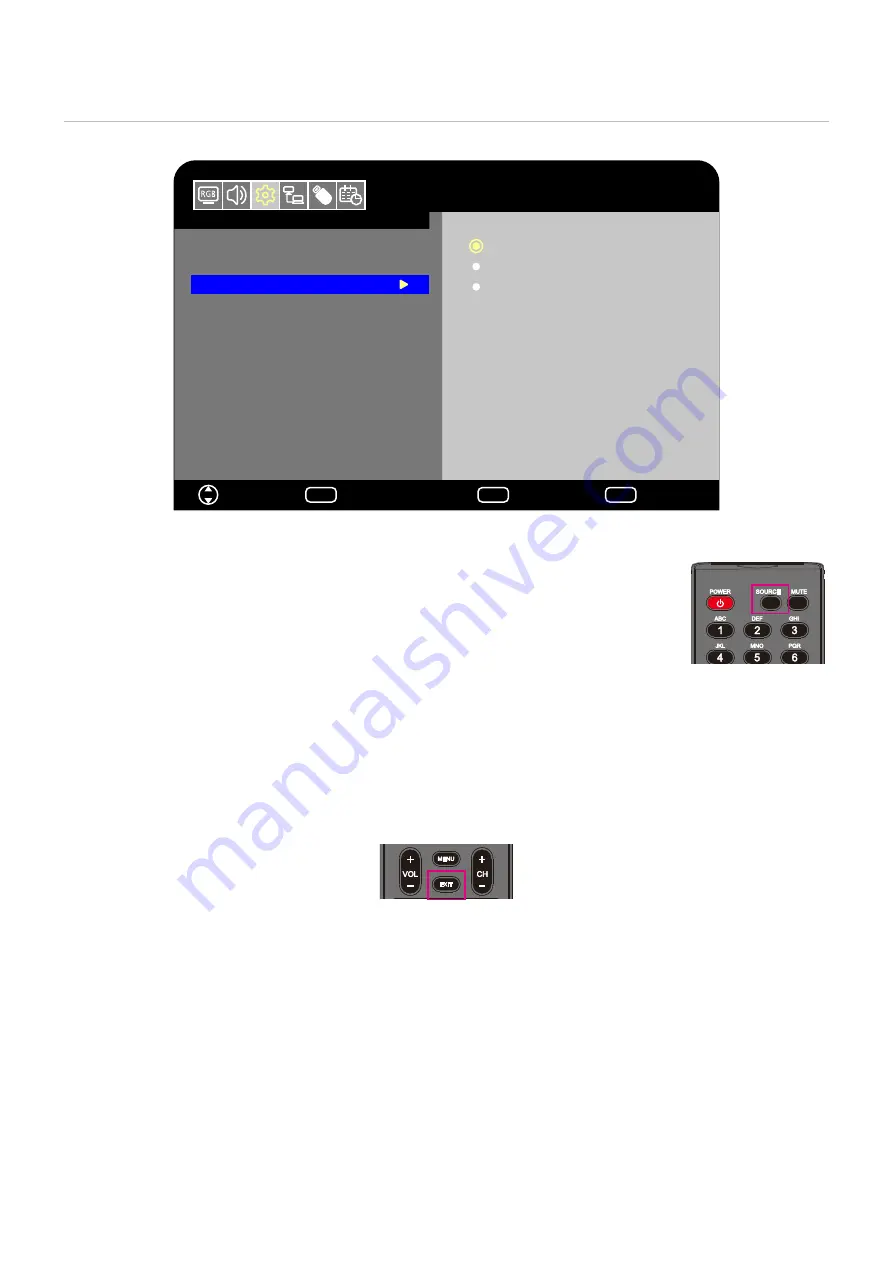
Locking the Remote Control Buttons

The [IR Lock Settings] prevent the monitor from being controlled using the remote control.

Setup

Move

Select

HDMI1

Input Labels
Key Lock Settings

IR Lock Settings

Power supply
LED Indicator
Mute Settings
Thermal Management
Signal Information

Off

OK

Return

MENU

EXIT

EXIT

Mode 1
Mode 2

1.  In the OSD menu, go to [Setup] -> [Other settings] and select [IR Lock Settings].
2.  Select the key lock range. 

•  OffE: All buttons operate normally.
•  Mode1E: Only the POWER and the SOURCE buttons operate.
•  Mode2E: All buttons are locked. (Only the power button can be used during standby mode.)
NOTEE:

The buttons are locked 3 seconds after Mode1 or Mode2 has been selected.

Unlocking the Remote Controls

Carry out the following with the monitor in On mode.
•  OSD menuE: To remove the lock and restore normal button operation, set the [IR Lock Settings] to [Off] using the monitor 

buttons.

•  Remote controlE: To remove the lock and restore normal button operation, hold the EXIT button pressed for 5 seconds or 

more.

Summary of Contents for 60005045

Page 1: ...User s Manual Digital Signage Display MODEL E328 E438 E498 E558 E658 ...

Page 2: ...layer 30 Connecting a USB Device 31 Chapter 4 Basic Operation Power On and Off Modes 33 Power indicator status 33 Energy Mode 33 When RS 232C is selected for control Power supply and Quick Start are set to Off 33 When LAN is selected for control Power supply and Quick Start are set to Off 34 Operating Range for the Remote Control 35 Showing the Information OSD 36 Switching Between Sound Modes 36 S...

Page 3: ...ycling and Energy Information Disposing of your old NEC product 82 Energy Saving 82 About Conversion Cables Used with the AV Terminal 84 NOTE 1 The contents of this manual may not be reprinted in part or whole without permission 2 The contents of this manual are subject to change without notice 3 Great care has been taken in the preparation of this manual however should you notice any questionable...

Page 4: ...echnician for help If necessary the user should contact the dealer or an experienced radio television technician for additional suggestions The user may find the following booklet prepared by the Federal Communications Commission helpful How to Identify and Resolve Radio TV Interference Problems This booklet is available from the U S Government Printing Office Washington D C 20402 Stock No 004 000...

Page 5: ...a mandatory action This symbol indicates that the power cord should be unplugged from the power outlet WARNING 1 UNPLUG THE POWER CORD Unplug the power cord if the product malfunctions Should the product emit smoke or strange odors or sounds or if the product has been dropped or the cabinet broken turn off the product s power then unplug the power cord from the power outlet Failure to do so could ...

Page 6: ...son Failure to follow the standard installation procedures could result in damage to the product or injury to the user or installer 8 Please install the product in accordance with the following information This product cannot be used or installed without the wall mount or other mounting accessory for support When transporting moving or installing the product please use as many people two or more p...

Page 7: ...using serious personal injury or death To prevent injury this product must be securely attached to the floor wall in accordance with the installation instructions Many injuries particularly to children can be avoided by taking simple precautions such as ALWAYS use wall mount or installation methods recommended by the manufacturer of the product set ALWAYS use furniture that can safely support the ...

Page 8: ...r water Immediately turn off the power and unplug your product from the wall outlet then refer servicing to qualified service personnel It may cause an electric shock or start a fire 12 Do not use flammable gas sprays to remove dust when cleaning the product Doing so could lead to a fire ...

Page 9: ...4 Do not climb on the table where the product is installed Do not install the product on a wheeled table if the wheels on the table have not been properly locked The product may fall causing damage to the product or personal injury 5 Installation removal and height adjustment of the optional wall mount When installing the wall mount handle the unit with care to avoid pinching your fingers 6 Do not...

Page 10: ...the product CAUTION Please use the power cord provided with this display in accordance with the table below If a power cord is not supplied with this equipment please contact your supplier For all other cases please use a power cord that matches the AC voltage of the power outlet and has been approved by and complies with the safety standard of your particular country Plug Type North America Europ...

Page 11: ...CD Screen When the LCD screen is dusty please gently wipe with a soft cloth Clean the LCD screen surface with a lint free non abrasive cloth Avoid using any cleaning solution or glass cleaner Please do not rub the LCD screen with a hard or abrasive material Please do not apply pressure to the LCD screen surface Please do not use OA cleaner as it will cause deterioration or discoloration on the LCD...

Page 12: ...3 Mounting for Trained Installers on page 14 Mounting Location on page 15 Orientation on page 16 Ventilation Requirements on page 17 Mounting on Walls or Ceilings on page 18 Attaching Mounting Accessories on page 19 NOTE For box contents please refer to the Setup Manual Product warranty does not cover damage caused by improper installation ...

Page 13: ...ries To install or replace batteries 1 3 4 2 CAUTION Please refer to CAUTION 8 NOTE The batteries supplied with the remote control may become empty quickly depending on their condition Therefore replace them with new batteries early If you do not intend to use the remote control for a long period of time remove the batteries 3 Connect external equipment To protect the external equipment disconnect...

Page 14: ...itor should be installed close to an easily accessible power outlet 5 Cable information CAUTION Use the provided specified cables with this product so as not to interfere with radio and television reception For mini D Sub 15 pin and USB use shielded signal cables with ferrite core For the HDMI and AV cables use shielded signal cables The use of other types of cables and adapters may cause receptio...

Page 15: ...shown for too long the Image Persistence will not disappear To avoid shortening the monitor s lifetime consider the following Turn off the main power of the monitor when not in use Use the button on the main unit or the button on the remote control to put the monitor in standby mode If you cover the panel surface of the main unit with a protective cover made of glass or acrylic the panel surface w...

Page 16: ...he qualified personnel or the supplier for service Depending on the environment the mounting location may weaken due to natural degradation Regularly ask the qualified personnel to inspect the mounting location and carry out maintenance NEC Display Solutions assumes no responsibility regarding any damage that may be caused by inadequate installation misuse modification of the product natural disas...

Page 17: ... support the weight of the monitor Prior to mounting inspect the installation location to ensure that it is strong enough to guaranty safety Pay attention not to obstruct part of the air vents of the monitor with the brackets For detailed information refer to the instructions included with the mounting equipment There are 4 installation holes on the back Mount the monitor evenly at the four locati...

Page 18: ...the monitor s handle use the handle locations shown in the figure below Fasten Force 120 190 N cm Possible locations for the handles used to attach the safety wire Attach the safety wire to the handles shown in the figure below E658 E558 Safety wire Mounting Location WARNING Please refer to WARNING 8 NOTE Allow for adequate ventilation or provide air conditioning around the monitor so that heat ca...

Page 19: ...NG Do not install it in the portrait orientation Otherwise it may cause a malfunction WARNING Do not install the monitor upside down The monitor cannot be used when inclined 10 or more WARNING Installing the monitor at an angle of 10 or more may cause a malfunction Within 10 Within 10 ...

Page 20: ...m environmental operating temperature of the monitor is 40 C This monitor has internal temperature sensors NOTE If the monitor overheats a Warning appears If a Warning appears stop using the monitor turn off the power and allow it to cool For more information on this function see Thermal Management page 77 If the monitor is used in an enclosed area or if the LCD panel is covered with an acrylic pr...

Page 21: ...NG Please refer to WARNING 8 1 Place a soft cloth on the table or another flat location where the monitor will be laid NOTE Make sure that the surface where you will lay the monitor is larger than the monitor screen When installing do not apply excessive force to any part of the monitor by pushing or leaning on it This may deform the monitor 2 Place the monitor on top of the soft cloth 3 Install t...

Page 22: ...a soft cloth such as a blanket that is larger than the monitor s screen area on the table before laying the monitor face down Make sure there is nothing on the table that can damage the monitor NOTE Prior to installation place the monitor face down on a flat even surface that is larger than the monitor screen Use a sturdy table that can easily support the weight of the monitor NOTE For use only wi...

Page 23: ...English 20 Chapter 2 Parts Names and Functions This Chapter Includes Control Panel on page 21 Terminal Panel on page 22 Wireless Remote Control on page 23 ...

Page 24: ... SET Button input switch button Central SET Operates as the setting button to execute the function selected when the OSD menu is open Left Right Move to the right or left of the OSD control menu Moving the left right keys left and right increases or decreases the adjustment values Up Down Move up and down in the OSD control menu Pressing the left right keys when the OSD menu is closed directly adj...

Page 25: ...mposite of a video player or other devices 7 HDMI input terminals HDMI1 ARC HDMI2 HDMI3 For connection to devices with digital video interface complying with the HDMI standard HDMI1 terminal also supports ARC Audio Return Channel for audio output Connect an HDMI cable supporting ARC to this terminal Connect audio devices supporting ARC to the HDMI1 ARC terminal NOTE ARC sends the monitor s sound t...

Page 26: ...ture modes are Dynamic Standard Energy Savings Conferencing HighBright Custom and HDR Video 9 p q t u OK cursor buttons Used to navigate inside and select the menus 0 VOL Button volume minus button VOL Button volume plus button Increases or decreases the audio output level MENU Button Opens and closes the OSD menu EXIT Button Closes the OSD menu CH Button CH Button Not used with this monitor EPG B...

Page 27: ...re connecting the monitor to the computer Refer to the externals equipment s user manuals for available connection types and instructions for each piece of equipment NOTE When the audio output connector of the connected audio device or computer is a stereo mini jack use an audio cable without a resistor Using an audio cable with a built in resistor may make it impossible to increase the volume or ...

Page 28: ...e your ears may be injured depending on the sound volume NOTE Headphones with a stereo mini jack plug can be connected to the monitor If the plug of your headphones is too large to enter the connector buy a 6 35 mm stereo jack plug to stereo mini jack plug adapter in your audio store The sound from the speakers is muted when headphones are connected Adjustment of the volume control as well as the ...

Page 29: ...utputting the HDMI signal Depending on the video card or driver used the image may not be shown correctly When you use a computer with HDMI go to the OSD menu Video Advanced Video and set Overscan to Auto or Off If the monitor s main power is turned on after the connected computer has been turned on the image may not be displayed In this case turn off the computer then turn it on again If the sour...

Page 30: ...on Connecting to Audio Equipment with ARC Function When audio equipment with the ARC function is connected to the HDMI1 ARC terminal of the monitor using the included ARC supported HDMI cable the speakers connected to the audio equipment outputs the monitor s sound The sound output via HDMI1 ARC is not adjustable with the OSD menu When the ARC function is activated the monitor s internal speakers ...

Page 31: ... control When the device search is complete connected devices are shown by their names 5 In the OSD menu select Yes under Search device When the device search is complete the HDMI terminals to which a device is connected are shown with the device name If no HDMI CEC compatible device is found make sure the device is connected turned on that it supports CEC and that CEC is enabled Depending on the ...

Page 32: ...Auto Turn Off System Standby If the monitor is set to standby using the remote control the HDMI CEC compatible device connected with an HDMI cable also goes into standby at the same time If the monitor goes into standby while an HDMI CEC compatible device is recording the device remains on Refer to the user s manual supplied with the HDMI CEC compatible device for further information In the OSD me...

Page 33: ...ore information on how to format a storage device see the manual or the help section of your Windows Use a USB storage device of the correct size in accordance with the drawing below If the physical size of the USB storage device is larger than the supported size shown below use a commercially available USB extension cable Connect the USB storage device to the USB Type A port of the monitor 70 mm ...

Page 34: ...on CAUTION Please refer to CAUTION 2 USB Type A port NOTE Check the connector shape and orientation when connecting the USB device or cable Do not connect a USB storage device to the monitor when the monitor is turned on To prevent damage to the monitor and possible corruption of the connected device s data files the monitor s main power switch should be off before making connections ...

Page 35: ...or the Remote Control on page 35 Showing the Information OSD on page 36 Switching Between Sound Modes on page 36 Switching Between Picture Modes on page 36 Setting the Aspect Ratio on page 37 OSD On Screen Display Controls on page 38 Using the Media Player Menu on page 40 Using the Media Player Menu on page 40 ...

Page 36: ...ries depending on the selected control method When RS 232C is selected for control Power supply and Quick Start are set to Off Home Office mode When no signal is input No signal is displayed and the monitor enters the auto standby mode after a while When a signal is input into the selected input terminal the On mode is resumed When the AV terminal and VGA YPbPr terminal are selected the On mode is...

Page 37: ...this case enable the Quick Start function With this function enabled the On mode is resumed Retail mode The monitor does not enter the energy saving mode when no signal is input The On mode is maintained Office mode When no signal is input No signal is displayed and the monitor enters the auto power save mode after a while The auto power save mode is maintained regardless of LAN signal input When ...

Page 38: ... 10 ft NOTE The remote control system may not function when direct sunlight or strong illumination strikes the remote control sensor or near fluorescent lamps Handling the remote control Do not expose to strong shock Do not allow water or other liquid to splash on the remote control If the remote control gets wet wipe it dry immediately Avoid exposure to heat and steam Ask your supplier or your mu...

Page 39: ...SD is set to On White Connected to a LAN Red Not connected to a LAN NOTE When the input signal is Media Player the information OSD will not be displayed Switching Between Sound Modes Press the SOUND button of the remote control to change the Sound Mode setting between Standard Music Movie and Custom Switching Between Picture Modes Press the PICTURE button of the remote control to change the Pictur...

Page 40: ...the image is enlarged There are no black bars neither vertically nor horizontally Part of the image vertically or horizontally is not displayed 4096 2160 1920 1080 1920 960 1024 768 3840 2160 3840 1920 3840 2025 2880 2160 3840 2025 1920 1080 1920 960 1024 768 3840 2160 3840 2160 3840 2160 3840 2160 3840 2160 3840 2160 3840 2160 3840 2160 4096 2160 1920 1080 1920 960 1024 768 3840 2160 3840 1920 38...

Page 41: ...nt Reset Video Settings HDR Video Dynamic Standard Energy Savings Conferencing HighBright Custom OK Return MENU EXIT EXIT Input source Selected main menu Sub menu Adjustment settings Key guide Main menu icons Wireless Remote Control Press MENU to open and close the OSD menu Press the EXIT button to close the OSD menu et stop OSD operations Press q to navigate through the sub menus Press the OK but...

Page 42: ...he other settings related to the image Audio settings Adjust the volume balance equalizer and the other settings related to the audio Setup settings Display the monitor information select the language or return the settings to their default values Control settings Configure settings such as the network information Media Player settings Configure the USB Demo Mode and other settings Schedule settin...

Page 43: ...ht an item in the operation menu and then press the OK button to select it Press the q button of the remote control to close the operation menu Slideshow Operation Select files using the p q t u buttons and press the button to start a slideshow Press the button to pause the slideshow To pause the slideshow using the OSD menu select Select to resume the slideshow Select or press the button of the r...

Page 44: ...les you checked are played once in the sorted order 1 Repeat one file A file is playing the current file plays on a loop No file is playing the highlighted file in the folder plays on a loop One or more selected files The first checked file in the sorted order plays on a loop A Repeat all files No selected files All files in the folder are played on a loop in the sorted order One or more selected ...

Page 45: ...eo MPEG1 40 Mbps 1920 x 1080 30 Hz MPEG2 40 Mbps 1920 x 1080 30 Hz MPEG4 40 Mbps 1920 x 1080 30 Hz H 263 40 Mbps 1920 x 1080 30 Hz H 264 135 Mbps 3840 x 2160 60 Hz HEVC H 265 100 Mbps 3840 x 2160 60 Hz Windows Media Video 9 WMV3 40 Mbps 1920 x 1080 30 Hz Audio codec Max bit rate of audio 2 Max channel No LPCM 1 5 Mbps 5 1 ch 1 MPEG1 2 Layer3 MP3 320 kbps 2 ch AAC AAC LC 576 kbps HE AAC v1 288 kbps...

Page 46: ...pter 5 Advanced Operation This Chapter Includes Creating a Power Schedule on page 44 Using Picture Modes on page 45 Setting Security and Locking the Monitor Controls on page 46 Locking the Button Controls on page 47 ...

Page 47: ...e time e imer Time settings le settings Power On Power Off ve Adjust Return MENU EXIT EXIT 12 00 12 00 Sleep Timer Current Time settings Schedule settings Move Adjust Power On Power Off Schedule HDMI1 Return MENU EXIT EXIT 12 00 12 00 Power On disabled Power On enabled b Use the t u buttons of the remote control to place the cursor on Power Off and then press the OK button of the remote control to...

Page 48: ...ct a mode HDR Video Dynamic Standard Energy Savings Conferencing HighBright Custom Picture Mode Types Picture Mode Purpose HDR Video Setting for HDR format video can be selected only when an HDR signal is input Dynamic High contrast video setting Standard Standard video setting Energy Savings Video setting complying with the International Energy Star standard Conferencing Video setting suited for ...

Page 49: ... any person using the remote control or the monitor control panel You can prevent unauthorized use and changes to the monitor settings by enabling the security and lock settings The security and locking functions covered in this section are Locking the monitor control panel buttons Locking the remote control buttons ...

Page 50: ...ment Signal Information Off Mode 1 Mode 2 HDMI1 OK Return MENU EXIT EXIT 1 In the OSD menu go to Setup Other settings and select Key Lock Settings 2 Select the key lock range Off All buttons operate normally Mode1 Only the power button and the input switching function operate Mode2 All buttons are locked Only the power button can be used during standby mode NOTE The buttons are locked 3 seconds af...

Page 51: ...gs 2 Select the key lock range Off All buttons operate normally Mode1 Only the POWER and the SOURCE buttons operate Mode2 All buttons are locked Only the power button can be used during standby mode NOTE The buttons are locked 3 seconds after Mode1 or Mode2 has been selected Unlocking the Remote Controls Carry out the following with the monitor in On mode OSD menu To remove the lock and restore no...

Page 52: ...N on page 51 HTTP Browser on page 52 Commands on page 56 Connecting an external device There are two options to connect an external device to control the monitor RS 232C Interface Connecting an external device to the RS 232C terminal of the monitor Network LAN Interface Connecting a network to the LAN port of the monitor with a LAN cable ...

Page 53: ...urn the computer on and then turn the monitor on Otherwise the COM port may not operate properly To control the monitor via commands sent from a computer connected with an RS 232C cable use the control commands Instructions for the control commands can be found in Commands in External Control in this manual or in External_ Control pdf see Appendix B External Resources page 71 RS 232C Cable Compute...

Page 54: ...u to receive email notifications from the monitor and control the monitor from a computer via a network To use a LAN connection you are required to assign an IP address to the monitor page 78 The monitor will obtain an IP address automatically when connected to a DHCP network NOTE Set Control Interface under Control Settings to LAN page 78 Example of LAN connection Server Hub NOTE NOTE Use a categ...

Page 55: ...strator The monitor may not respond if the buttons shown on the browser are repeatedly pressed in rapid intervals In such a case wait a moment and try again If you still can t get a response turn the monitor off and then back on If the monitor Network Settings screen does not appear in the Web browser press the Ctrl F5 keys to refresh your Web browser To control the monitor via a LAN see External_...

Page 56: ...Top INPUT SOURCE HDMI1 STATUS PROTOCOL STATUS SYSTEM MODEL NAME E438 SERIAL XX3XXXXXXX FIRMWARE VERSION Vx x x Vx x x LOCAL TIME WWW MMM DD XX XX XX 20YY UPTIME XXh XXm XXs NETWORK IP ADDRESS 192 168 0 10 SUBNET MASK 255 255 255 0 DEFAULT GATEWAY 0 0 0 0 DNS PRIMARY 0 0 0 0 DNS SECONDARY 0 0 0 0 MAC Address XX XX XX XX XX XX NETWORK SYSTEM LOGOUT TCP ROOMVIEW CRESTRON CONTROL AMX NAME OVERVIEW NOT...

Page 57: ...ork when Off is selected for DHCP SUBNET MASK Set the subnet mask for the network to which the monitor is connected when Off is selected for DHCP DEFAULT GATEWAY Set the default gateway for the network to which the monitor is connected when Off is selected for DHCP Enter 0 0 0 0 to delete the setting DNS PRIMARY Enter the IP address of the primary DNS server of the network connected to the monitor...

Page 58: ...ed only for use with Crestron s ROOMVIEW For further information visit http www crestron com AMX Settings Click on AMX on the left hand column on the HOME screen to enter the setting screen AMX BEACON When the monitor is connected to a network supporting the NetLinx control system by AMX enables or disables the function to send a beacon to the system from AMX Device Discovery NOTE When using a dev...

Page 59: ...om a connected device Instructions for each command format can be found in External_Control pdf in our Website see Appendix B External Resources page 71 RS 232C Interface Item Details PROTOCOL RS 232C BAUD RATE 9600 bps DATA LENGTH 8 bits PARITY NONE STOP BIT 1 bit FLOW CONTROL NONE Network LAN Interface Item Details PROTOCOL TCP PORT NUMBER 7142 COMMUNICATION SPEED AUTO setting 10 100Mbps ...

Page 60: ... on page 58 The image is not displayed correctly on page 59 An instruction or caution screen is displayed on page 60 Others when connected to a computer on page 60 Others remote control speakers on page 60 Others when connected via RS 232C or LAN on page 61 When using a media player on page 61 When using a video device on page 61 ...

Page 61: ...eo settings P 74 If the image is not displayed after adjusting Backlight Brightness and Contrast in the OSD menu check that the connected device operates correctly If the monitor is connected to a computer check the frequency resolution and type of output signal on the computer P 26 The power indicator is lit a color other than blue or is flashing The power management function may be functioning P...

Page 62: ...isplayed properly the monitor may malfunction Contact your supplier If the OSD menu is displayed properly the monitor is not malfunctioning Select Color and adjust the colors as needed or execute Reset Video Settings under the Video settings to return the settings to their default values P 74 P 74 If the OSD menu is displayed properly and the computer screen does not appear correctly after executi...

Page 63: ...use a malfunction P 77 1 Depending on the computer a proper signal may not be output immediately after changing the resolution or the frequency and the caution may be displayed for a while In such a case wait for a while If the screen display returns to normal it means the input signal is proper Others when connected to a computer Symptom Cause Solution I cannot change the resolution or the number...

Page 64: ...olution Reference The media player function does not recognize the USB storage device Check that a USB storage device is correctly connected to the USB port P 30 When using a video device Symptom Cause and solution Reference There is no image and no sound Check that the external device video player etc is correctly connected and operates properly For more information see the manual of the external...

Page 65: ...English 62 Chapter 8 Specifications This Chapter Includes Compatible Signal List on page 63 E328 on page 65 E438 on page 66 E498 on page 67 E558 on page 68 E658 on page 69 ...

Page 66: ...ate Hz Component HDMI video E328 E438 E498 E558 E658 640 x 480p 60 720 x 480i 60 720 x 480p 60 720 x 576i 50 720 x 576p 50 1280 x 720p 50 1280 x 720p 60 1920 x 1080i 50 60 24 25 1920 x 1080p 30 50 60 24 25 3840 x 2160p 30 50 60 24 25 4096 x 2160p 30 50 60 ...

Page 67: ...0 1280 x 960 60 1280 x 1024 60 75 1400 x 1050 60 RB 1440 x 900 60 1600 x 1200 60 1680 x 1050 60 1920 x 1080 60 3840 x 2160 30 60 1366 x 768 60 1920 x 1440 60 2560 x 1600 60 RB Reduced blanking signal NOTE Depending on the input signal s resolution characters may look blurred or figures may be distorted Depending on the video card or driver used the image may not be shown correctly ...

Page 68: ...Digital audio signal PCM 2 ch 32 44 1 48 kHz 16 20 24 bits Audio output Stereo Mini Jack 3 5 mm Ø Analog audio signal For headphones output S PDIF terminal Digital audio signal For digital audio output HDMI ARC terminal 3 Digital audio signal PCM 2 ch 32 44 1 48 kHz 16 20 24 bits Speaker Output Internal Speakers 5 W 5 W Stereo Control Terminals RS 232C 9 Pin D sub x1 LAN RJ 45 10BASE T 100BASE TX ...

Page 69: ...nal PCM 2 ch 32 44 1 48 kHz 16 20 24 bits Audio output Stereo Mini Jack 3 5 mm Ø Analog audio signal For headphones output S PDIF terminal Digital audio signal For digital audio output HDMI ARC terminal 3 Digital audio signal PCM 2 ch 32 44 1 48 kHz 16 20 24 bits Speaker Output Internal Speakers 10 W 10 W Stereo Control Terminals RS 232C 9 Pin D sub x1 LAN RJ 45 10BASE T 100BASE TX USB Terminal US...

Page 70: ...nal PCM 2 ch 32 44 1 48 kHz 16 20 24 bits Audio output Stereo Mini Jack 3 5 mm Ø Analog audio signal For headphones output S PDIF terminal Digital audio signal For digital audio output HDMI ARC terminal 3 Digital audio signal PCM 2 ch 32 44 1 48 kHz 16 20 24 bits Speaker Output Internal Speakers 10 W 10 W Stereo Control Terminals RS 232C 9 Pin D sub x1 LAN RJ 45 10BASE T 100BASE TX USB Terminal US...

Page 71: ...nal PCM 2 ch 32 44 1 48 kHz 16 20 24 bits Audio output Stereo Mini Jack 3 5 mm Ø Analog audio signal For headphones output S PDIF terminal Digital audio signal For digital audio output HDMI ARC terminal 3 Digital audio signal PCM 2 ch 32 44 1 48 kHz 16 20 24 bits Speaker Output Internal Speakers 10 W 10 W Stereo Control Terminals RS 232C 9 Pin D sub x1 LAN RJ 45 10BASE T 100BASE TX USB Terminal US...

Page 72: ...nal PCM 2 ch 32 44 1 48 kHz 16 20 24 bits Audio output Stereo Mini Jack 3 5 mm Ø Analog audio signal For headphones output S PDIF terminal Digital audio signal For digital audio output HDMI ARC terminal 3 Digital audio signal PCM 2 ch 32 44 1 48 kHz 16 20 24 bits Speaker Output Internal Speakers 10 W 10 W Stereo Control Terminals RS 232C 9 Pin D sub x1 LAN RJ 45 10BASE T 100BASE TX USB Terminal US...

Page 73: ...ncluded in this product 1 MPEG AVC THIS PRODUCT IS LICENSED UNDER THE AVC PATENT PORTFOLIO LICENSE FOR THE PERSONAL USE OF A CONSUMER OR OTHER USES IN WHICH IT DOES NOT RECEIVE REMUNERATION TO i ENCODE VIDEO IN COMPLIANCE WITH THE AVC STANDARD AVC VIDEO AND OR ii DECODE AVC VIDEO THAT WAS ENCODED BY A CONSUMER ENGAGED IN A PERSONAL ACTIVITY AND OR WAS OBTAINED FROM A VIDEO PROVIDER LICENSED TO PRO...

Page 74: ...y controlling and querying the monitor via either RS 232C or LAN The protocol uses encoded binary and requires calculation of checksums and most functionality in the monitor can be controlled using these commands This document is available for download from the NEC Display Solutions Website in your region Software Software is available for download on the NEC Display Solutions global Website https...

Page 75: ...ols List This Chapter Includes Video Settings on page 73 Audio Settings on page 75 Setup on page 76 Control Settings on page 78 Media Player on page 79 Schedule on page 80 See the NEC Display Solutions Website for the default values ...

Page 76: ...e aspect ratio 1 1 Shows the image in a 1 by 1 pixel format If the input resolution is higher than the recommended resolution the image will be scaled down to fit the screen Full Fills the entire screen even if the aspect ratio needs to be changed Zoom Fills the entire screen without changing the aspect ratio NOTE The areas of the image that are outside of the active screen area are not shown Over...

Page 77: ...thin the room When set to On the brightness of the screen is adjusted automatically according to the room brightness NOTE When set to ON Backlight Brightness cannot be changed Color Enhance Changes the colors of the image and the saturation to create a more colorful image HDR Mode When the monitor detects an HDR signal you can select preferred gamma correction from Low Mid and High Backlight Brigh...

Page 78: ...udio Internal Speakers Configures the settings for the internal speakers output Auto The sound is not output from the speakers when a cable is connected to the HEADPHONE terminal Off Sound is not output from the speakers On Sound is always output from the speakers Digital Output Select the optical digital audio format of the S PDIF terminal RAW Outputs in the RAW format PCM Outputs in the PCM form...

Page 79: ... the selected input terminal on the Information OSD None The input terminal is changed manually First If the signal is lost in the input terminal being displayed the monitor searches automatically another terminal with an input signal and switches to it The display does not change if a new signal is input into a terminal different from the terminal currently being displayed Custom The input termin...

Page 80: ...sing the buttons on the monitor control panel Off All buttons operate normally Mode 1 Only the power button and the input switching function operate Mode 2 All buttons are locked Only the power button can be used during standby mode IR Lock Settings Prevents the monitor from being controlled using the remote control Off All buttons operate normally Mode 1 Only the POWER and the SOURCE buttons oper...

Page 81: ...net mask for the network to which the monitor is connected when Off is selected for DHCP DEFAULT GATEWAY Set the default gateway for the network to which the monitor is connected when Off is selected for DHCP DNS PRIMARY Enter the IP address of the primary DNS server of the network connected to the monitor NOTE Enter 0 0 0 0 to delete the setting DNS SECONDARY Enter the IP address of the secondary...

Page 82: ...signal is being input in a terminal other than the USB port There was no user operation for 10 seconds or more NOTE Memo The POWER VOLUME and MUTE buttons of the remote control operate normally If other buttons are pressed the playback stops and the input returns to the terminal used previously The playback is also stopped is the USB storage device is removed If the monitor is turned off during pl...

Page 83: ...inutes 240 minutes can be selected Current Time settings Sets the current time NOTE If the monitor remains for two weeks or more with the power cord unplugged the clock will not show the correct time In this case set the Current Time settings again Schedule settings Power On Sets the time when the monitor will turn on Power Off Sets the time when the monitor will turn off ...

Page 84: ...ISPLAY SOLUTIONS is strongly committed to environmental protection and sees recycling as one of the company s top priorities in trying to minimize the burden placed on the environment We are engaged in developing environmentally friendly products and always strive to help define and comply with the latest independent standards from agencies such as ISO International Organization for Standardizatio...

Page 85: ... greenvision en greenvision xhtml in Europe https www nec display com in Japan https www necdisplay com in USA Energy Saving This monitor features an advanced energy saving capability When a Display Power Management signal is sent to the monitor the Energy Saving mode is activated The monitor enters a single Energy Saving mode For additional information visit https www necdisplay com in USA https ...

Page 86: ... products may only apply to the current European Union Member States uct or if applicable follow applicable legislation or agreement you may have The mark on electrical and electronic products may only apply to the current European Union Member States Outside the European Union If you wish to dispose of used electrical and electronic products outside the European Union please contact your local au...

Page 87: ...cables to connect to the AV terminal Check the wiring specification of the cable in advance and choose a proper cable NOTE Different wiring specifications may exist for 4 contact mini jack cables No Signal 1 Video 2 Audio left 3 Audio right 4 GND 1 2 3 4 Example of RCA connectors male 4 contact mini jack cable Example of RCA connectors female 4 contact mini jack cable ...

Page 88: ...English 85 Rev 3 1 ...

Reviews: