


E-21
SET UP Settings Menu
Setting the language for the menus
The menu display can be set to one of eight languages.
Example: Setting the menu display to “DEUTSCH”
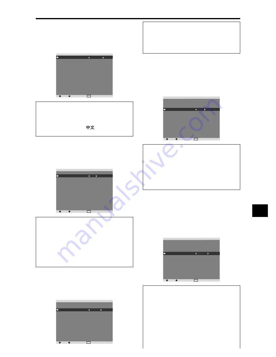
On “LANGUAGE” of “SET UP” menu, select “DEUTSCH”.
SEL.
ADJ.
EXIT RETURN
S E T U P
L A N G UAG E
B N C I N P U T
D - S U B I N P U T
H D S E L E C T
R G B S E L E C T
DV I S E T U P
C O L O R S Y S T E M
BAC K G RO U N D
G R AY L E V E L
S 1 / S 2
D I S P L AY O S M
O S M A D J.
A L L R E S E T
: D E U T S C H
: C O M P O N E N T
: R G B
: 1 0 8 0
I
: AU TO
: AU TO
: G R AY
: 3
: O F F
: O N
: TO P L E F T
: O F F
Information
䡵
Language settings
ENGLISH ........
English
DEUTSCH .......
German
FRANÇAIS ......
French
ESPAÑOL .......
Spanish
ITALIANO ........
Italian
SVENSKA .......
Swedish
................... Chinese
У ............
Russian
Setting the BNC connectors
Select whether to set the input of the 5 BNC connectors to
RGB and component or SCART1, 2.
Example: Set the BNC INPUT mode to “RGB”
On “BNC INPUT” of “SET UP” menu, select “RGB”.
SEL.
ADJ.
EXIT RETURN
S E T U P
L A N G UAG E
B N C I N P U T
D - S U B I N P U T
H D S E L E C T
R G B S E L E C T
DV I S E T U P
C O L O R S Y S T E M
BAC K G RO U N D
G R AY L E V E L
S 1 / S 2
D I S P L AY O S M
O S M A D J.
A L L R E S E T
: E N G L I S H
: R G B
: R G B
: 1 0 8 0
I
: AU TO
: AU TO
: G R AY
: 3
: O F F
: O N
: TO P L E F T
: O F F
Information
䡵
BNC INPUT Settings
RGB:
Use the 5BNC terminals for RGB input.
COMPONENT:
Use the 3BNC terminals for
component input.
SCART1:
Use the 4BNC terminals for RGB with
composite sync. See page E-7.
SCART2:
Use the 3BNC terminals for RGB and the
VIDEO1 terminal for composite sync. See page E-7.
Setting the RGB1 connector
Select one of the signals being transmitted to the RGB1
terminal.
Example: Set the D-SUB INPUT mode to “SCART3”
On “D-SUB INPUT” of “SET UP” menu, select “SCART3”.
S E T U P
L A N G UAG E
B N C I N P U T
D - S U B I N P U T
H D S E L E C T
R G B S E L E C T
DV I S E T U P
C O L O R S Y S T E M
BAC K G RO U N D
G R AY L E V E L
S 1 / S 2
D I S P L AY O S M
O S M A D J.
A L L R E S E T
: E N G L I S H
: C O M P O N E N T
: S C A RT 3
: 1 0 8 0
I
: AU TO
: AU TO
: G R AY
: 3
: O F F
: O N
: TO P L E F T
: O F F
SEL.
ADJ.
EXIT RETURN
Setting high definition images to the suitable
screen size
Use this procedure to set whether the number of vertical
lines of the input high definition image is 1080I or 1035I
or 540P.
Example: Setting the “HD SELECT” mode to “1035I”
On “HD SELECT” of “SET UP” menu, select “1035I”.
SEL.
ADJ.
EXIT RETURN
S E T U P
L A N G UAG E
B N C I N P U T
D - S U B I N P U T
H D S E L E C T
R G B S E L E C T
DV I S E T U P
C O L O R S Y S T E M
BAC K G RO U N D
G R AY L E V E L
S 1 / S 2
D I S P L AY O S M
O S M A D J.
A L L R E S E T
: E N G L I S H
: C O M P O N E N T
: R G B
: 1 0 3 5
I
: AU TO
: AU TO
: G R AY
: 3
: O F F
: O N
: TO P L E F T
: O F F
Information
䡵
HD SELECT modes
These 3 modes are not displayed in correct image
automatically.
1080I:
Standard digital broadcasts
1035I:
Japanese “High Vision” signal format
540P:
Special Digital broadcasts (for example :
DTC100)
Information
䡵
D-SUB INPUT Settings
RGB:
Use the D-SUB terminal for RGB input.
SCART3:
Use the D-SUB terminal for RGB signal fed
from SCART. See page E-7.
Setting a computer image to the correct RGB
select screen
With the computer image, select the RGB Select mode
for a moving image such as (video) mode, wide mode or
digital broadcast.
Example: Setting the “RGB SELECT” mode to
“MOTION ”
On “RGB SELECT” of “SET UP” menu, select “MOTION”.
SEL.
ADJ.
EXIT RETURN
S E T U P
L A N G UAG E
B N C I N P U T
D - S U B I N P U T
H D S E L E C T
R G B S E L E C T
DV I S E T U P
C O L O R S Y S T E M
BAC K G RO U N D
G R AY L E V E L
S 1 / S 2
D I S P L AY O S M
O S M A D J.
A L L R E S E T
: E N G L I S H
: C O M P O N E N T
: R G B
: 1 0 8 0
I
: M OT I O N
1 0 2 4
ⴒ
7 6 8
: AU TO
: G R AY
: 3
: O F F
: O N
: TO P L E F T
: O F F
Information
䡵
RGB SELECT modes
One of these 7 modes must be selected in order to
display the following signals correctly.
AUTO:
Select the suitable mode for the specifications
of input signals as listed in the table “Computer input
signals supported by this system” on page E-2 of Model
Information.
STILL:
To display VESA standard signals. (Use this
mode for a still image from a computer.)
MOTION:
The video signal (from a scan converter)


