background image

30 / 45

30

| Set up and Installation

Linking the primary and secondary display

1. Tap the 

INPUT

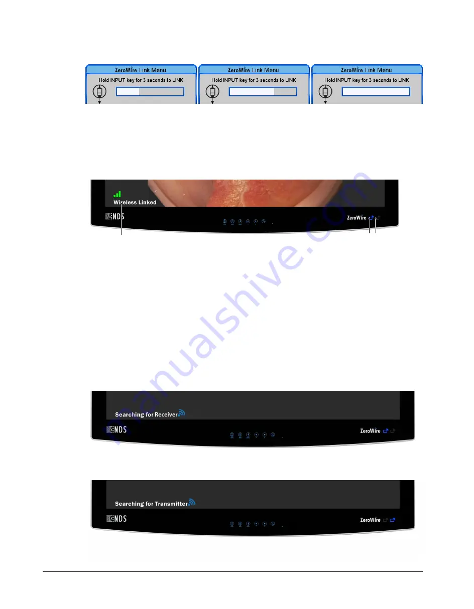
 button on the primary display. ZeroWire Link Menu will appear on the screen.

2. Push and hold the 

INPUT

 button for three seconds to search for a secondary (receiving) display and activ-

ate the link. The white bar indicates the linking progress.

3. Wait until the white bar is full then follow the same steps on the secondary display.

Wireless Linking Status Messages

(1)

(2)(3)

(1)

Status message indicating the stages of the linking process.

(2)

Tx Indicator

(3)

Rx Indicator

In the lower left corner of the display, a series of status messages will indicate stages of the linking process. In
the lower right corner of the display, there are two blue LED indicators. The left corresponds to the TX indic-
ator and the right corresponds to the RX indicator. These indicators light up when the display is set to a ZW in-
put.

Stage 1:

When initiating a link, the typical sequence of status messages presented on the display begins with 

Search-

ing for Transmitter

  (secondary  display)  or 

Searching for Receiver

  (primary  display).  The  corresponding  Tx

and Rx indicator will blink slowly indicating each display is set to a ZW input and searching for a pair.

Summary of Contents for RADIANCE ULTRA 32 4K ZEROWIRE DUO

Page 1: ...Radiance Ultra 32 4K ZeroWire Duo Instructions for Use ENGLISH ...

Page 2: ......

Page 3: ...e without notice NDS provides this informa tion as reference only Reference to products from other vendors does not imply any recommendation or endorsement This document contains proprietary information protected by copyright No part of this manual may be re produced by any mechanical electronic or other means in any form without prior written permission of NDS All trademarks are the property of t...

Page 4: ......

Page 5: ...anufacture YYYY MM DD Catalogue number Serial number Batch code Atmospheric pressure limitation Humidity limitation Temperature limit Waste management Fragile Keep dry This way up Complies to IEC 60601 1 including US and Cana dian deviations in their respective valid version The Canadian Standards Association CSA certi fication mark represents safety approval by Cana dian Standards Associ ation fo...

Page 6: ...tative No hazardous sub stances contained in the device Contains restricted sub stances The symbol number refers in years to the Environmental Protection Use Period EPUP during which the product can be safely used and following which should be imme diately recycled Equipotentiality Closed On Switch Open Off Switch Protective earth pro tective ground Alternating current Non ionizing electro magneti...

Page 7: ...s 24 6 4 Electrical Symbols 25 7 Set up and Installation 26 7 1 Positioning and Orientation 26 7 2 Non Line of Sight Operation 28 7 3 Setting up and linking the displays 29 8 Display Specifications 32 9 ZeroWire Specifications 33 10 Supported Resolutions 35 11 Installation and Maintenance 37 11 1 VESA Mounting 37 11 2 Cable Cover Installation 37 11 3 Cleaning Instructions 37 12 Troubleshooting 38 ...

Page 8: ......

Page 9: ... to modify the appearance graphics and technical data of the product through continued development of its products Please note Paragraphs marked with the words WARNING CAUTION and NOTE carry special meanings Sec tions marked with these words must be given special attention WARNING The safety and or health of the patient user or a third party are at risk Comply with this warning to avoid injury to ...

Page 10: ... maintenance schedules are not adhered to The handing over of technical documents does not constitute authorization to make repairs adjustments or alterations to the device or accessories peripherals WARNING Modification of the device is not permitted Only an authorized service technician may perform repairs adjustments or alterations on the device or ac cessories peripherals and use the service m...

Page 11: ...hock Do not touch any part inside the unit To reduce the risk of electric shock DO NOT re move the cover or back WARNING For mission critical applications we strongly recommend that a replacement ZeroWire 4k Display Pair and a DVI cable be immediately available Additionally we recommend that a display that is hard wired to the video source be immediately available whenever a surgical procedure is ...

Page 12: ...e Refer servicing to qualified service personnel NOTE This product is designed to meet medical safety requirements for a patient vicinity device Do not use in MR Environments Hereby NDS Surgical Imaging LLC declares that this ZeroWire 4K System is in compliance with the essential requirements and other relevant provisions of Directive 2014 53 EU The full text of the EU Declaration of Con formity i...

Page 13: ... your power source The power cord is the only recognized disconnect device for this product To power off the product dis connect the power cord from the AC mains The product and other medical equipment should be positioned so that the power cord and connection to AC mains is readily accessible If an extension cord or power strip is needed for connection of this product to AC mains confirm that the...

Page 14: ...ntended for delivery of video signals from a source such as an endoscopy camera processor or other video source over a radio frequency link to a ZeroWire Receiver for display of images during endoscopic and general surgical procedures The Radiance Ultra 32 4K ZeroWire Duo is a non sterile reuasable device not intended for use in the sterile field ...

Page 15: ...y displayed with details of the current input listed above the menu tabs SCROLL Button Vertical Selection Control To enter a menu tap the SCROLL button The top parameter row is selected with first tap of the SCROLL button and the selection moves downward to the next row with each successive tap To exit a menu use the SCROLL button to move the selection to the bottom menu row and then tap the SCROL...

Page 16: ...ton to enter the menu To adjust a parameter tap the SCROLL button to move the row selection down to it and then tap the or button to adjust the parameter or select a setting Parameter adjustments are applied in real time while chan ging values or settings The OSD Menu closes automatically 30 seconds after the last action or can be closed by tapping the MENU button NOTE Grayed out descriptions indi...

Page 17: ...fills the screen while retaining the aspect ratio The image may be displayed as letterboxed with black bars top and bottom or left and right 1 1 Displays the video data in its native size and aspect ratio Images with resolution less than the 4K UHD native 3840 x 2160 resolution are displayed with a black background surrounding the image NOTE Scaling options are limited to Aspect when overscan sett...

Page 18: ...olor temperatures User With a preset color temperature selected if any other color parameter is subsequently adjusted from the default setting the resulting values are copied to the color temperature User presets and User is selected Red Green Blue To adjust balance of the selected color in the image tap the or button Saturation available only for YUV inputs To adjust saturation color intensity of...

Page 19: ... the color correction feature BT 709 Factory calibrated to meet the BT 709 standard BT 2020 Factory calibrated to emulate the BT 2020 standard Auto Color Correction When Auto Color Correction is ON color correction will be selected based on the input signal Auto Color Correction Settings by Input and resolution type HDMI 1 HDMI 2 Display Port 1 Display Port 2 DVI 12G SDI ZW Re ceiver Graphic NDS N...

Page 20: ...ignal a DPMS message displays for 10 15 seconds be fore the display goes into Power Saving mode The display turns on when the input signal is restored Menu Lock To enable Menu Lock Tap the button Off Default setting On Disables access to all OSD menus except the Input Menu The OSD Menu closes and a MENU LOCKED message displays briefly To unlock OSD access simultaneously press the MENU and SCROLL b...

Page 21: ...ower To activate the Zero Wire Power tap the button On is displayed in blue font Off is displayed in grey font To deactivate the Zero Wire Power tap the button Off is displayed in blue font On is displayed in grey font Select On for both the transmitting primary display and the receiving secondary display to initiate the link ing and transmission of video 5 8 Input Menu Open the Input Menu directl...

Page 22: ...ay To activate the ZW AutoLink tap the button On is displayed in blue font Off is displayed in grey font To deactivate the ZW AutoLink tap the button Off is displayed in blue font On is displayed in grey font Color Domain Format The following settings are available on all inputs Auto Select this option to automatically detect the signal color space This option is unavailable when using the SDI and...

Page 23: ... SERVICE 2 Connector designated for installing firmware upgrades 6 RS 232 6 pin modular connector used for Unified Serial Command USC input 7 SERVICE 1 Connector designated for installing firmware upgrades 8 DISPLAY PORT Input accepts a DisplayPort 1 2a signal to display 9 HDMI Input accepts a HDMI 1 4b signal to display 10 DVI IN Input accepts a DVI 1 0 signal to display 11 DVI OUT Output is acti...

Page 24: ...gative 3 ML_Lane 0 n Lane 0 negative 13 CONFIG1 Ground 4 ML_Lane 1 p Lane 1 positive 14 CONFIG2 Ground 5 GND Ground 15 AUX CH p Auxiliary Channel posit ive 6 ML_Lane 1 n Lane 1 negative 16 GND Ground 7 ML_Lane 2 p Lane 2 positive 17 AUX CH n Auxiliary Channel neg ative 8 GND Ground 18 Hot Plug Hot Plug Detect 9 ML_Lane 2 n Lane 2 negative 19 Return Return for Power 10 ML_Lane 3 p Lane 3 positive 2...

Page 25: ...lug detect all versions 10 TMDS Clock DVI D Digital DVI D IN Supports digital signals Pin Signal Pin Signal Pin Signal 1 T M D S DATA 2 11 T M D S DATA 1 3 SHIELD 21 Not used 2 T M D S DATA 2 12 Not used 22 T M D S CLOCK SHIELD 3 T M D S DATA 2 4 SHIELD 13 Not used 23 T M D S CLOCK 4 Not used 14 5V POWER 24 T M D S CLOCK 5 Not used 15 GND DVI I IN Only 6 DDC CLOCK 16 HOT PLUG DETECT C1 Not used 7 ...

Page 26: ...ction 5 GND Signal Ground USB Micro AB Pin Name Description 1 VCC 5 Vdc 2 D Data Transmit Return 3 D Data Transmit 4 Not used No Connection 5 GND Signal Ground 6 pin Modular RS 232 Serial Control 6 pin Modular Serial Command Adapter Cable Pin Name Description 1 N C No Connection 2 N C No Connection 3 N C No Connection 4 RXD Receive 5 GND Ground 6 TXD Transmit ...

Page 27: ...ound post Closed On Switch This symbol appears on the closed or on side of the display On Off switch Open Off Switch This symbol appears on the open or off side of the display On Off switch CAUTION Degradation of the video signal We recommend that the bend radius of metallic cables be no less than 2 5 inches 63 mm or 7 times the diameter of the cable whichever is greater Sharper bends may damage t...

Page 28: ...rimary and secondary displays should be installed so they are aligned vertically and horizontally within 10 Vertical Alignment Vertical alignment should be within 10 Horizontal Alignment Horizontal alignment should be within 10 10 0 10 1 2 Display alignment 1 Primary display 2 Secondary display 1 2 Viewing cone 1 Primary display 2 Field Shape ...

Page 29: ... with a horizontal distance between the displays of up to 30 feet 9 1 m However in the case of most OR environments best results are achieved with a hori zontal distance of up to 8 feet 2 4 m To avoid loss of image or flickering minimize line of sight obstruction between primary and secondary display Min 5 ft 1 5 m Max 8 ft 2 4 m Min 5 ft 1 5 m 1 2 5 4 3 Positioning of displays 1 Radiance Ultra 32...

Page 30: ...ck the wireless signals if they obstruct the line of sight between the primary and secondary display see illustration below Preferably surgical lights should be positioned out of the way or raised above the line of sight If an object must obstruct the line of sight the best option is to position it half way between the primary and secondary display OR rooms whose walls and or ceiling are construct...

Page 31: ... Input Menu 19 on the primary display 3 Select either Tx 12G SDI ZW Tx DisplayPort ZW or Tx HDMI ZW by selecting one of the three Tx ZW op tions 4 Open the SETUP tab see Setup Menu 18 5 Ensure ZeroWire Power is set to On If not set ZeroWire Power to On Setting up the secondary receiving display The secondary display will receive the video transmitted from the primary display wirelessly 1 Open the ...

Page 32: ...ng process 2 Tx Indicator 3 Rx Indicator In the lower left corner of the display a series of status messages will indicate stages of the linking process In the lower right corner of the display there are two blue LED indicators The left corresponds to the TX indic ator and the right corresponds to the RX indicator These indicators light up when the display is set to a ZW in put Stage 1 When initia...

Page 33: ... 65 connection quality an icon will appear indicating the quality of the wireless link If a link cannot be established or verified within 60 seconds the No Receiver Found or No Transmitter Found status message will be presented on the primary and secondary display respectively If the linked displays lose connection Signal Lost will be presented on both displays NOTE If the linking process failed r...

Page 34: ...nal 1350 1 Typical Luminance cd m2 700 Color Gamut 149 of BT 709 Pixel Pitch 0 1845 mm DC Input 24 V 6 25 A DC Power Consumption Typical a 130 W Monitor Weight 32 0 lb 14 5 kg Monitor Dimensions W x H x D 30 7 x 20 x 3 4 780 x 509 x 87 mm Temperature Rangesb Operating 32 104 F 0 40 C Storage Transport 4 122 F 20 50 C Humidity Ranges Non condensing b Operating 20 90 Storage Transport 10 90 Altitude...

Page 35: ... EIRP Maximum Range 30 ft 9 14m Data Rate 50 Mbps 3 8 Gb s Power Consumption 8 Watts Maximum EIPR Output Power of Test Frequency Channels Frequency Range Average EIRP Output Power LRP Sink 60 16 62 96 GHz 22 7 dBm LRP Source 60 16 62 96 GHz 21 9 dBm MRP HRP Source 60 48 62 64 GHz 28 7 dBm Noninterference Distance The listed devices on the following table have been tested to demonstrate the minimum...

Page 36: ...within the room 3 Groups of two Radiance Ultra 32 4K ZeroWire Duo systems may be set in multiple rooms providing the rooms are spaced at least 25 ft 7 6 m apart 4 Radiance Ultra 32 4K ZeroWire Duo displays should not be installed in metal cabinets or surrounded by metallic objects as this will prevent communication between the displays Multi System Installation When two paired Radiance Ultra 32 4K...

Page 37: ...n 1920 x 1080 25 000 74 176 High definition 1920 x 1080 33 716 29 970 74 176 High definition 1920 x 1080 33 750 30 000 74 250 High definition 1920 x 1080 56 250 50 000 148 500 High definition 1920 x 1080 67 433 59 940 148 352 High definition 1920 x 1080 67 500 60 000 148 500 Graphic 640 x 480 31 500 60 000 25 200 Graphic 640 x 480 37 861 72 809 31 500 Graphic 640 x 480 37 500 75 000 31 500 Graphic...

Page 38: ...it 4 4 4 HDMI DP Ultra high definition 4K DCI 4096x2160 50fps YCbCr 10bit 4 2 2 HDMI DP Ultra high definition UHD 3840x2160 60fps RGB 8bit 4 4 4 HDMI DP Ultra high definition UHD 3840x2160 59 94fps RGB 8bit 4 4 4 HDMI DP Ultra high definition UHD 3840x2160 50fps RGB 8bit 4 4 4 HDMI DP Ultra high definition UHD 3840x2160 30fps RGB 8bit 4 4 4 HDMI DP Ultra high definition UHD 3840x2160 60fps YCbCr 1...

Page 39: ...ble cover to the cable well recess on the back of the display 3 Position cables under the cut out and slide the cover forward into the recess until tabs on the bottom edge click into place 11 3 Cleaning Instructions Prior to cleaning the monitor must be turned OFF and disconnected from the power source Clean the front glass and enclosure with a lint free cloth lightly dampened with distilled water...

Page 40: ... after attempting to pair The primary and second ary display cannot nego tiate the RF Channel to connect on Cycle both Radiance Ultra 32 4K ZeroWire Duo display s power Poor or intermittent video The primary and second ary display are spaced more than 30 feet 9 1 m apart Reduce the spacing between the displays to 30 feet 9 1 m or less See Maximum Range in section Specifications The primary and sec...

Page 41: ...er might need to take mitigation measures such as relocating or re orienting the equipment The following EMC tables are provided for your reference 13 1 Guidance and Manufacturer s Declaration Electromagnetic Emissions The product is intended for use in an environment as described below The user operator of the product should make sure the device is operated within such an environment Emissions te...

Page 42: ...e 0 5 1 2 kV 0 5 1 kV Conducted RF IEC 61000 4 6 3 V 0 15 MHz 80 M Hz 6 V ISM Bands 80 AM 1 kHz Power frequency 50 60 Hz magnetic field IEC 61000 4 8 30 A m 50 or 60 Hz Voltage dips short interruptions and voltage vari ations on power supply input lines IEC 61000 4 11 100 dip 0 5 periods 0 45 90 135 180 225 270 315 100 dip 1 period 30 dip 25 30 periods 50 60 Hz Interrupt 100 drop 5 s NOTE Field st...

Page 43: ... devices can have an effect on the performance characteristics of the device Therefore such devices must be kept a minimum distance of 30 cm independ ent of any calculation from the insufflator its accessories and cables Rated maximum output power W of transmitter Separation distance in meters according to frequency of transmitter 150kHz to 80 MHz 80 MHz to 800 MHz 800 MHz to 2 7 GHz 0 01 0 12 0 1...

Page 44: ... interference by one or more of the following measures Reorient or relocate the receiving antenna Increase the separation between the equipment and receiver Connect the equipment into an outlet on a circuit different from that to which the receiver is connected Consult your dealer or an experienced radio TV technician for help Accessory equipment connected to this product must be certified accordi...

Page 45: ...AR PURPOSE AND NON INFRINGEMENT WITH RESPECT TO ALL NDS PRODUCTS OR SERVICES ANY AND ALL OTHER WARRANTIES REPRESENTATIONS AND OR GUARANTEES OF ANY TYPE NATURE OR EX TENT BE IT IMPLIED EXPRESS AND OR WHETHER ARISING UNDER OR AS A RESULT OF ANY STATUTE LAW COM MERCIAL USAGE CUSTOM TRADE OR OTHERWISE ARE HEREBY EXPRESSLY EXCLUDED AND DISCLAIMED NDS its suppliers and or distributors are not liable dir...

Page 46: ......

Page 47: ......

Page 48: ...H Werk 4 92442 Wackersdorf Germany Tel 49 9431 7984 0 info novanta europe novanta com Asia Pacific Novanta Japan East Square Omori 6 20 14 Minamioi Shinagawa ku Tokyo 140 0013 Japan 81 3 5753 2466 info ndssi com Oriental Media Center Suite 1510 Tower C No 4 Guang Hua Road Chao Yang District Beijing 100026 China 86 10 8559 7859 info ndssi com NDS Quality System ISO 13485 FDA Registration 2954921 ...

Reviews: