background image

NCR


Proprietary


Information

 ‐ 

not


to


be


disclosed


or


reproduced


without


written


consent.


©


2017,


2018


by


NCR


Corporation,


Atlanta,


Georgia,


U.S.A.


http://www.ncr.com.All


Rights


Reserved

B006

7519

G000

Variant


Details

 ‐ 

CEN


I,


Standard


Collar


ATM


NCR


SelfServ™


84


Walk

Up


ATM


Site


Preparation

9

 ‐ 

6

SERVICING


AREAS

 ‐ 

OPTIMUM

 ‐ 

SINGLE


ATM

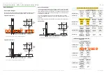
The


optimum


servicing


area


provides


the


best


access


to


the


ATM


for


all


servicing


and


operation


tasks.

Wherever


possible


the


ATM


should


be


installed


within


the


optimum


servicing


area.

If


the


optimum


area


is


not


available


then


refer


to


Servicing


Areas

 ‐ 

Minimum.


However


note


that


installing


the


ATM


in


the


minimum


servicing


area


may


increase


the


servicing


and/or


upgrading


time


over


a


ATM


installed


using


the


optimum


area.


Always


leave


as


much


space


as


possible


around


the


ATM


to


facilitate


safe


operation


and


servicing.

Short


Sleeve

Long


Sleeve

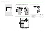
750 mm

(29.53 in.)

460 mm

(18.11 in.)

326 mm

(12.83 in.)

1000 mm

(39.37 in.)

2352 mm

(92.60 in.)

203 mm

(7.99 in.)

Maximum

1780 mm

(70.08 in.)

770 mm

(30.31 in.)

525 mm

(20.67 in.)

460 mm

(18.11 in.)

90 mm

(3.54 in.)

25 mm

(0.98 in.)

Rear of

security

enclosure

(door open)

750 mm

(29.53 in.)

460 mm

(18.11 in.)

326 mm

(12.83 in.)

1000 mm

(39.37 in.)

2466 mm

(97.09 in.)

330 mm

(12.99 in.)

Maximum

1780 mm

(70.08 in.)

770 mm

(30.31 in.)

525 mm

(20.67 in.)

460 mm

(18.11 in.)

90 mm

(3.54 in.)

25 mm

(0.98 in.)

Rear of

security

enclosure

(door open)

Summary of Contents for SelfServ 84 Walk-Up

Page 1: ...NCR SelfServ 84 Walk Up Standard Collar ATM Site Preparation B006 7519 G000...

Page 2: ...NCR s copyright notice must be included It is the policy of NCR Corporation NCR to improve products as new technology components software and firmware become available NCR therefore reserves the right...

Page 3: ...onths 5 2 Transit Range Up To One Week 5 2 Extreme Power On Range Up To One Hour 5 2 Barometric Pressure 5 2 Power Requirements AC Power Requirements 6 1 Input Voltage Setting 6 1 Grounding 6 1 Transi...

Page 4: ...h page has two or three columns laid out as follows Where left and right side are stated the ATM is viewed from the front facia side of the ATM All plan views are from the top unless otherwise stated...

Page 5: ...The responsibility for ensuring that the site is prepared in compliance with this document remains with the customer For information and guidance purposes only a list is provided in general terms of...

Page 6: ...ds The ATM complies with the following requirements for radiated and conducted immunity EN 55024 1998 A1 2001 A2 2003 As per the requirements of EN55024 the ATM complies with the requirements of the f...

Page 7: ...e with a medium to high feature functionality configuration Heat dissipation figures are largely unaffected by transactional rates PRODUCT IDENTIFICATION The illustration below is typical of the layou...

Page 8: ...M can be found in the Variant Details sections DOORWAYS AND CORRIDORS Make sure that doorways and corridors leading to your point of installation are wide enough to allow the package to pass through o...

Page 9: ...d humidity to a maximum humidity at 0 C 32 F Normal Operating Range Interior Environment Temperature 0 C to 40 C 32 F to 104 F Relative Humidity 20 to 80 Dew Point Temperature Restriction 26 C 79 F ma...

Page 10: ...termittent short circuits and switching transients can be introduced on to power lines Such transient energy can be very damaging to electronic hardware and can also cause data corruption Under these...

Page 11: ...ne of two options a basic alarm system or an enhanced alarm system A stabilised non interruptible power supply must be provided through the external alarm system The alarm interface cable wiring must...

Page 12: ...rm to the following specification and wiring Remove a 20 mm 0 79 in section of the outer sleeve 100 mm 3 94 in from the ATM end of the cable Take care not to cut through the cable shielding ETHERNET S...

Page 13: ...rif typeface should be used Tiresias is recommended The text size should be at least 14 point and larger where possible Where tactile decals are required they should be designed in line with specific...

Page 14: ...7 in 770 mm 30 31 in 832 mm 32 76 in 664 mm 26 14 in 800 mm 31 50 in 801 mm 31 54 in 259 mm 10 20 in 226 mm 8 90 in 66 mm 2 60 in Note 1 60 mm 2 36 in 681 mm 26 81 in 502 mm 19 76 in 62 mm 2 44 in Not...

Page 15: ...7 in 165 mm 6 50 in Contactless Card Reader behind Facia 915 mm 36 02 in 1033 mm 40 67 in 165 mm 6 50 in PIN Pad Number 5 Key 849 mm 33 43 in 967 mm 38 07 in 136 5 mm 5 37 in Private Audio 780 mm 30 7...

Page 16: ...high tensile minimum ISO property class 8 8 Washers Type flat steel as per DIN7349 or equivalent Size M16 5 8 in Outer diameter no greater than 40 mm 1 58 in Minimum thickness 6 mm 0 2 in BOLT HOLES T...

Page 17: ...mum 12 99 in 203 mm 330 mm 534 mm 21 02 in B 18 mm 0 71 in 625 mm 24 61 in A Hole in Wall ATM Base View from Inside Building Plinth Sidewalk increase to 635 mm 25 00 in if ATM installed with cash came...

Page 18: ...hown assume the ATM is being moved using equipment that does not extend beyond the ATM or packaging A surrounding clearance of 6 mm 0 24 in has been allowed in the dimensions 47 mm 1 85 in 31 5 mm 1 2...

Page 19: ...Minimum However note that installing the ATM in the minimum servicing area may increase the servicing and or upgrading time over a ATM installed using the optimum area Always leave as much space as p...

Page 20: ...note that installing the ATM in the minimum servicing area may increase the servicing and or upgrading time over a ATM installed using the optimum area Always leave as much space as possible around t...

Page 21: ...Maximum 110 mm 4 33 in 1080 mm 42 52 in 110 mm 4 33 in 770 mm 30 31 in 375 mm 14 76 in 2 3 175 mm 6 89 in 375 mm 14 76 in 1520 mm 59 84 in 2026 mm 79 76 in 2352 mm 92 60 in denotes small 10 volume in...

Page 22: ...110 mm 4 33 in 70 mm 2 76 in 770 mm 30 31 in 2 1b 375 mm 14 76 in 2026 mm 79 76 in 326 mm 12 83 in 175 mm 6 89 in 2360 mm 92 91 in 110 mm 4 33 in 175 mm 6 89 in 450 mm 17 72 in 3 760 mm 29 92 in deno...

Reviews: