


Site Preparation
53
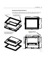
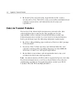
Mounting Specification Illustrations
The following illustration shows the minimum allowable dimensions
for the display opening when the optional cosmetic bezel is used.
19100
348.7 mm
3.730 in.
4.2 mm
.165 in.
9.4 mm
.372 in.
270 mm
10.630 in.
345.4 mm
13.600 in.
156.2 mm
6.150 in.
141.6 mm
5.575 in.
292.4 mm
11.510 in.
17.2 mm
.678 in.
200.7 mm
7.900 in.
175 mm
6.888 in.
22.9 mm
.900 in.
FRONT SURFACE OF DISPLAY BEZEL (IF USED)
MUST PROTRUDE THROUGH ENCLOSURE. GASKET
MUST MEET INSIDE SURFACE OF CUSTOM
APPLICATION'S DISPLAY OPENING. THIS IS
TO PROVIDE A SECURE AND WATERTIGHT FIT.
OPTIONAL COSMETIC BEZEL
GASKET MUST MEET INSIDE SURFACE
OF CUSTOM DISPLAY OPENING.
(OPTIONAL COSMETIC GASKET NOT USED
IF OPTIONAL BEZEL IS NOT USED).
USE 4 #8-32 MACHINE SCREWS IN
CORNERS OF UNIT TO MOUNT DISPLAY
INTO ENCLOSURE. 8 TOTAL SCREWS
MAY BE USED FOR MULTIPLE MOUNTING
CONFIGURATIONS.
Summary of Contents for EasyPoint 7401
Page 1: ...NCR EasyPoint 7401 Release 2 4 Site Preparation Guide 19797 NCR B005 0000 1255 Issue C...
Page 8: ...vi Site Preparation...
Page 20: ...2 Site Preparation 7401 45xx Model 19889d...
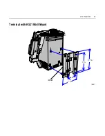
Page 57: ...Site Preparation 39 Terminal with K521 Wall Mount 19291 7 in 8 7 in 4 in 7 8 in K521...
Page 62: ...44 Site Preparation Mounting Screw on both sides 17735 K525 with K530 Pole Mount Straps...
Page 84: ......
Page 89: ......
Page 90: ...B005 0000 1255 May 2002 Printed on recycled paper...


