


4-78
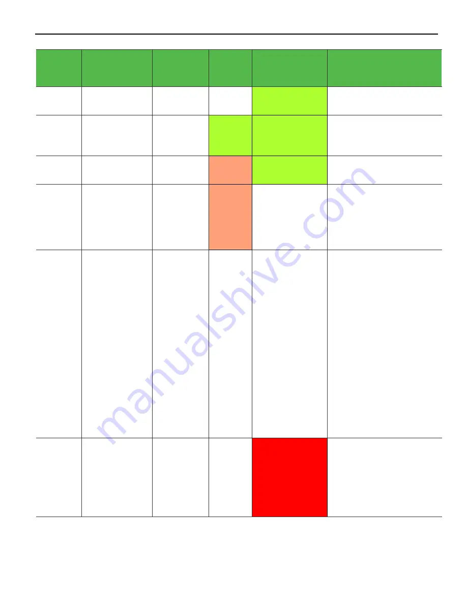
Diagnostics
Current
System
Operation
Suspect
Component/
Failure
Terminal
State
Disk
Activity
LED
Power LED
Debug Path
Normal
Operation
N/A
System ON
OFF
ON
N/A
Normal
Operation
N/A
System ON
with HDD
Activity
Flashing
(HDD
Access)
ON
N/A
Normal
Operation
N/A
Unit in
Suspend (S3)
ON
Blinking (1/Sec)
N/A
OFF with
AC
Present
N/A
OFF Not in
Standby
External
power
supply ON
ON
OFF
N/A
OFF
AC
Present
Power System
OFF
Not in
Standby
External
power
supply ON
OFF
OFF
•
Check AC power to
power supply.
•
Check Power supply.
•
Check connection
between unit and power
supply.
•
Check power connection
from connector panel to
motherboard and
motherboard to LED
panel.
•
Replace power supply.
•
Replace motherboard.
•
Replace front panel
board.
Runtime
Cooling
Component/CPU
Over
Temperature
N/A
Flashes
red/green, then
solid red as
temperature
increases
•
Check for blocked
cooling Vents.
•
Check for fan failure.
•
Check for excessive
ambient temperature.
•
Check cooling solution.
Summary of Contents for 7607
Page 1: ...User Guide NCR POS XR8 XR8c 7607 B005 0000 2436 Issue C ...
Page 9: ...vii Touch Screen Cleaning Procedures 141 ...
Page 27: ...Chapter 2 External Connectors Motherboard Release 1 x Release 2 x Display Port Connections ...
Page 28: ...2 18 External Connectors Release 3 x XR8c ...
Page 42: ...2 32 ...
Page 59: ...Hardware Installation 3 49 24V Powered USB and RS232 Cables ...
Page 61: ...Hardware Installation 3 51 24V Powered USB and RS232 Cables ...
Page 70: ...3 60 Hardware Installation NCR 5932 5715 Big Ticket USB Keyboard ...
Page 72: ...3 62 Hardware Installation NCR 5932 6674 POS Compact Alphanumeric USB Keyboard ...
Page 77: ...Hardware Installation 3 67 3 Disconnect the SATA Power connector from the Drive ...
Page 78: ...3 68 Hardware Installation 4 Unscrew the Drive from the Hard Drive chassis Retain the screws ...
Page 79: ...Hardware Installation 3 69 5 Slide the drive out of the chassis bracket ...
Page 80: ...3 70 Hardware Installation 6 Slide in the new drive and secure with the retained screws ...
Page 81: ...Hardware Installation 3 71 7 Connect the SATA Power connector to the Drive ...
Page 82: ...3 72 Hardware Installation 8 Replace the Sled Cover and reconnect power to the terminal ...
Page 92: ...5 82 ...
Page 130: ...7 120 ...
Page 147: ...Configuring a Second HDD for RAID 10 137 7 Select Next ...
Page 152: ...11 142 ...


