background image


Revision 1.6.4 

VPOS Touch User Manual 

                    Page 2 

Table of Contents 

General Information ............................................................................................................................. 3


Organization of the Manual ............................................................................................................. 3


Device Overview ................................................................................................................................... 4


Device Summary ............................................................................................................................... 4


Device Specifications ........................................................................................................................ 5


Device Components ......................................................................................................................... 7


Device Serial Number ....................................................................................................................... 8


Device Cables.................................................................................................................................... 9


Device Connector Scheme (40-Pin) ................................................................................................ 10


Additional Accessories (Included in Box) ....................................................................................... 10


Getting Started ................................................................................................................................... 12


Installation ...................................................................................................................................... 12


Device Dismantling ......................................................................................................................... 12


Operating and Testing .................................................................................................................... 12


Configure VPOS Touch Settings in NayaxVend .............................................................................. 13


Technician Mode ............................................................................................................................ 14


Appendix 1 

 Tests Prior to Repair ..................................................................................................... 15


Appendix 2 - FCC & IC Regulations ..................................................................................................... 17


Safety and Handling Instructions ....................................................................................................... 19


Environmental Guidelines .............................................................................................................. 19


Warranty and Liability .................................................................................................................... 19


Cleaning Instructions ...................................................................................................................... 19


Summary of Contents for VPOS Touch

Page 1: ...VPOS Touch All in one Card Reader with Touch Screen and Telemetry Device VPOS Touch User Manual Property of Nayax All rights reserved For more information contact us at support nayax com...

Page 2: ...ice Cables 9 Device Connector Scheme 40 Pin 10 Additional Accessories Included in Box 10 Getting Started 12 Installation 12 Device Dismantling 12 Operating and Testing 12 Configure VPOS Touch Settings...

Page 3: ...ich the manual is intended Device Overview section provides an overview of the device The summary outlines the uses of the hardware and software requirements device configuration and device behavior i...

Page 4: ...ss cards The advantages of using the device are enabling easy installation monitoring machines in real time and a complete management solution Our complete management solution consists of Inventory Ma...

Page 5: ...Display Screen High quality color touch LCD Display 2 4 inch IPS 400 nits 320 x 240 pixels 4 LEDs 6 Touch buttons Architectutre ARM Technology 2x Cortex 32 bit 180 216MHz Audio Speaker Buzzer Localiz...

Page 6: ...ulse input output interfaces 1 Inhibit input External Sensors Support 1 Door open 1 Temperature Communication 3G 4G Ethernet NFC Machine Protocols MDB DEX DDCMP Pulse VCCS ccTalk JVMA Payments Contact...

Page 7: ...nents Front Panel Front Panel Color Yellow Black Rear Side M4 x 5 mm Typical Hole LAN SIM Speaker SAM Connector SD Card Connect or Cable Connector Antenna Magnetic stripe Contact slot stripe Touch but...

Page 8: ...er Manual Page 8 Device 2D Scheme Device Serial Number Serial number logic PPMAPOWWYYSSSSSS Characters Description PP Product Type E g For VPOS Touch 04 MA Main HW Version PO POS HW Version WW Week Nu...

Page 9: ...t different machines The below table refers to each cable and its configuration Image Connector Connect to MDB MDB in vending machines JVMA JVMA in vending machines Japan DEX DEX RS232 DB9 Female Seri...

Page 10: ...Revision 1 6 4 VPOS Touch User Manual Page 10 Device Connector Scheme 40 Pin Additional Accessories Included in Box Rear Plate Drilling Template Stencil...

Page 11: ...Revision 1 6 4 VPOS Touch User Manual Page 11 Additional Accessories Optional Reclining Spacer Angle 7 5 degrees Protective Box...

Page 12: ...urn on the machine 2 Once the VPOS Touch is powered up a Self Test is automatically initiated that performs a SIM card and Server Connectivity check Note If the device is not installed correctly you m...

Page 13: ...function Support Phone Number Displays the phone number that is visible under the Menu Contact Us function Technician Code Controls the pin code to access the Technician mode screen Menu Timeout Contr...

Page 14: ...sted below Icon Icon Name Description Cash Collection Indicates to the server that cash was collected Poll Initiate Keep Alive communication with the server Reboot Checks for updated device version in...

Page 15: ...FW OK II Init mdm III RSSI 99 In this case there are three options to proceed a RSSI 99 Check the External Antenna Adapter connected to the board Refer to Image 2 b SIM RST This could refer to a SIM i...

Page 16: ...he External Antenna adapter connects to the board and to the External Antenna that is provided by Nayax 3 Sim Housing The SIM socket is opened by pulling up and closed by puling down the socket 3 Test...

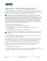
Page 17: ...he following measures Reorient or relocate the receiving antenna Increase the separation between the equipment and receiver Connect the equipment into an outlet on a circuit different from that to whi...

Page 18: ...POS Touch IDs are FCC ID 2AK6L VPOST IC 10840A VPOST The VPOS Touch device is available with two cellular modules These are the two options Contain FCC ID RI7LE910NAV2 Contains IC 5131A LE910SNAV2 Con...

Page 19: ...nsing conditions Warranty and Liability Thank you for choosing Nayax Read the Nayax 24 months Limited Warranty Terms and Limitations included in your contract In the unlikely event that your device ne...

Reviews: