NAVTELECOM SMART S-2420 Operation Manual Download Page 21


3.


LED


INDICATION 


In order to display the operation modes and the current state of the system, three LEDs on the device case are used: 

SYS, GSM and NAV. 

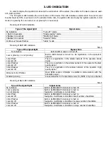
The SYS system LED indicates the current status of the device. This LED indicates an alarm state if an alert is sent 

to subscribers by SMS, or an input is in the activated state. Also, the system LED can display the system operation in test 

mode (it is glowing for one second, is not glowing for one second). 


Meaning of SYS LED indication 

Tab. 3 

Type of the signal light 

Signal value 

No indication 

“Turn off ” mode 

1 flash in 4 seconds 

“Energy saving” mode  

2 flashes in 4 seconds 

“Monitoring” mode  

3 flashes in 4 seconds 

“Security” mode  

Continuous frequent flashes 

“Alarm” mode  


Meaning of GSM LED indication 

Tab. 4 

Type of the signal light 

Signal value 

No indication 

Built-in GSM-module is turned off.  

1 sec is glowing, 1 is not glowing 

Built-in  GSM-module  is  turned  on.  No  registration  in  the  operator's 

network 

1 short flash 

1 second off 

There is a registration in the cellular network of the operator. Weak 

signal 

2 short flashes 
1 second off 

There is a registration in the cellular network of the operator. Medium 
quality signal 

3 short flashes 

1 second off 

There  is  a  registration  in  the  cellular  network  of  the  operator.  High 

quality signal 

Permanent short flashes 

Open  GPRS  session.  Attempts  to  establish  communication  with  the 

telematics server 

Constant glowing 

Connected either to the telematics server by GPRS or by voice channel 


Meaning of NAV LED indication 

Tab. 5 

Type of the signal light 

Signal value 

No indication 

Built-in GLONASS/GPS module is turned off 

1 sec is glowing 

1 is not glowing 

Built-in GLONASS/GPS module is turned on 

Navigation coordinates is not identified 

1 short flash 

1 second off 

Built-in GLONASS/GPS module is turned on 

Navigation coordinates is identified. Small number of satellites 

2 short flashes 

1 second off 

Built-in GLONASS/GPS module is turned on 

Navigation coordinates is identified. Average number of satellites 

3 short flashes 

1 second off 

Built-in GLONASS/GPS module is turned on 

Navigation coordinates is identified. A large number of satellites 


Summary of Contents for SMART S-2420

Page 1: ...GPS GLONASS TRACKING EQUIPMENT SMART S 2420 Operations manual Installation and connection of the device v1 0 MOSCOW 2020...

Page 2: ...terested in constantly improvement of the manufactured products quality Please contact our technical support by email address support navtelecom ru should you have any questions or problems with the d...

Page 3: ...et 7 1 7 Device components 9 1 8 Device interface connector 11 2 CONNECTION OF THE DEVICE 12 2 1 Installation 12 2 2 SIM card installation and operation 13 2 3 Power connection 13 2 4 Universal inputs...

Page 4: ...passenger s safety 1 3 Operational principles The device during its operation continuously monitors the status of the connected sensors vehicle battery voltage GSM modem signal level operational capa...

Page 5: ...7 Current consumption at 12 V voltage in operation mode on Average2 mA 80 Current consumption at 12 V voltage with turned off GLONASS and GSM modules is no more than mA 20 Maximum current consumption...

Page 6: ...voltage is exceeded the power protection is activated The device continues to work but is powered by the battery 2 If GPRS operates in poor communications peak consumption 10 ms consumption of the de...

Page 7: ...iniUSB connector for connection with a computer SIM card holder slot with ejector yellow button In the upper part of the device unit figure 3 there are three indicators system indicator SYS modem oper...

Page 8: ...res 1 4 Interface cable with MiniUSB connector 1 5 Passport 1 6 Package 1 Figure 4 14 pin connector of Microfit 14 Figure 5 Interface cable with MiniUSB connector Some cases may require connection of...

Page 9: ...gure 7 Fuel level sensor Figure 8 External LED The manufacturer reserves the right to complete the devices with equipment whose set appearance and characteristics differ from those shown in the figure...

Page 10: ...res 9 12 1 front cover 2 fixing hole 3 system LED indicator 4 GSM LED indicator 5 GLONASS GPS LED indicator 6 14 pin connector 7 MiniUSB connector 8 SIM card 1 ejector holder 9 SIM card holder 1 exter...

Page 11: ...Figure 11 Figure 12...

Page 12: ...ency It allows to connect to them a wide range of different sensors for example frequency frequency from 1 Hz to 2000 Hz and analog voltage from 0 V to 31 V FLS impulse fuel consumption sensors DRL bu...

Page 13: ...places with an ambient temperature more than 60 C for example near heating systems etc It is also prohibited to place the device in a sealed container without heat dissipation It is prohibited to inst...

Page 14: ...chnical characteristics When voltage surges which is more than the specified ratings occur the built in overvoltage protection system will operate in the device It is strongly recommended to connect t...

Page 15: ...measurement event become available CPU_adc R1 R2 UIN C1 U Figure 14 Connection of analog sensors 2 4 2 Discrete sensors connection The device allows to connect any type of sensors that have two stead...

Page 16: ...algorithms for example when they are averaged at parking lots energy saving when calculating engine hours and in some other device algorithms Any input which configured for operation with a discrete...

Page 17: ...lay of the track depends on its settings In addition to virtual sensors accelerometer is used for such functions as EcoDriving For proper operation of these functions the accelerometer must be calibra...

Page 18: ...e If the power source is vehicle s on board network the LED must be connected through current limiting resistor Such resistor is already installed inside the lamp in the automotive LED lamps It is onl...

Page 19: ...contacts are always marked as 30 87 and 87a The 30th pin is always in the relay Without applying voltage to the winding contacts it is permanently closed to contact 87a If a signal is applied to the...

Page 20: ...30 85 86 87a 87 14 7 13 6 12 5 11 4 10 3 9 8 2 1 Fuse 1A GND Car battery Diode 1N4007 Fuse External device GND Figure 30 Connection diagram of the relay to the outputs of the device OUT1 and OUT2...

Page 21: ...cond off There is a registration in the cellular network of the operator Weak signal 2 short flashes 1 second off There is a registration in the cellular network of the operator Medium quality signal...

Reviews: