background image

FCC Statement

Note: This equipment has been tested and found to comply with the limits for a Class B digital 
device, pursuant to Part 15 of the FCC Rules. These limits are designed to provide reasonable 
protection against harmful interference in a normal installation. This equipment generates, 
uses and can radiate radio frequency energy and, if not installed and used in accordance with 
the instructions, may cause harmful interference to radio communications. However, there is 
no guarantee that interference will not occur in a particular installation. If this equipment does 
cause harmful interference to radio or television reception, which can be determined by turning 
the equipment off and on, the user is encouraged to try to correct the interference by one or 
more of the following measures:

Reorient or relocate the receiving antenna.
Increase the separation between the equipment and receiver.
Connect the equipment into an output on a circuit different from that to which the 
receiver is connected.
Consult the dealer or an experienced technician for help.
A shielded cable must be used when connecting a peripheral to the 
serial ports.

IMPORTANT

It is the owner’s sole responsibility to install and use the instrument and transducer(s) in a 
manner that will not cause accidents, personal injury or property damage. The user of this 
product is solely responsible for observing safe boating practices.

NAVMAN NZ LIMITED DISCLAIMS ALL LIABILITY FOR ANY USE OF THIS PRODUCT IN A 
WAY THAT MAY CAUSE ACCIDENTS, DAMAGE OR THAT MAY VIOLATE THE LAW.

Governing Language: This statement, any instruction manuals, user guides and other 
information relating to the product (Documentation) may be translated to, or has been translated 
from, another language (Translation). In the event of any con ict between any Translation 
of the Documentation, the English language version of the Documentation will be the of cial 
version of the Documentation.

Fuel Computer:

 Fuel economy can alter drastically depending on the boat loading and 

sea conditions.  The fuel computer should not be the sole source of information concerning 
available fuel onboard and the electronic information should be supplemented by visual or 
other checks of the fuel load. This is necessary due to possible operator induced errors such 
as forgetting to reset the fuel used when  lling the tank, running the engine with the fuel 
computer not switched on or other operator controlled actions that may render the device 
inaccurate. Always ensure that adequate fuel is carried onboard for the intended trip plus a 
reserve to allow for unforeseen circumstances.

This manual represents the FISH 4500/4600 as at the time of printing. Navman NZ Limited 
reserves the right to make changes to speci cations without notice.

Copyright © 2004 Navman NZ Limited, New Zealand. All rights reserved. Navman is a 
registered trademark of Navman NZ Limited.

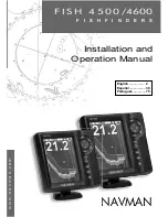
This is the Installation and Operation manual for the Navman FISH 4500 and FISH 4600 (here 
after referred to as FISH 4500/4600)  sh nders. The FISH 4500/4600 is set up with default 
units of feet, °F (Fahrenheit), US gallons and knots. See section 3-6 Setup > Units, to change 
the units.

Summary of Contents for FISH 4500/4600

Page 1: ...VMAN TRACKFISH 6600 C H A R T P L O T T E R A N D F I S H F I N D E R Installation and Operation Manual w w w n a v m a n c o m F I S H 4 5 0 0 4600 F I S H F I N D E R S English 2 Español 38 Português 75 ...

Page 2: ...N A WAY THAT MAY CAUSE ACCIDENTS DAMAGE OR THAT MAY VIOLATE THE LAW Governing Language This statement any instruction manuals user guides and other information relating to the product Documentation may be translated to or has been translated from another language Translation In the event of any con ict between any Translation of the Documentation the English language version of the Documentation w...

Page 3: ...e Displays 22 5 1 Sonar display 22 5 2 Sonar Zoom display 23 5 3 Sonar Bottom display 24 5 4 Sonar 50 200 display 24 5 5 Sonar A Scope display 24 5 6 Fuel display 25 5 7 Data display 25 5 8 About display 26 6 Installation and Maintenance 27 6 1 What comes with this product 27 6 2 Options and Accessories 27 6 3 Mounting and removing the display unit 27 6 4 Power and transducer connections 28 6 5 Wi...

Page 4: ...finder that the transducer is installed in the best location Please follow the installation instructions very carefully This manual also explains how to operate the FISH 4500 4600 effectively and provides trou bleshooting information and performance tips The Navman fishfinder can also assist with navigation by providing depth information to help identify the depth contours marked on charts The FIS...

Page 5: ...o has been returned the next pulse is sent The FISH 4500 4600 converts each echo into an electronic signal displayed as a vertical line of pixels The most recent echo appears on the extreme right of the display with the older echoes being scrolled towards the left eventually disap pearing off the display The scroll speed depends upon the water depth and scroll speed setting See section 3 2 Setup S...

Page 6: ...d or setting and to make the change s 2 Press ENT to confirm ESC to cancel Power On Auto Power Press to turn the fishfinder on If the fishfinder is wired for auto power it turns on automatically whenever the boat s ignition is turned on This ensures that the engine hours counter and optional fuel functions are activated A title display appears briefly This is followed automatically by the Installa...

Page 7: ...e mode Use this when on the move The FISH 4500 4600 prominently displays the water depth and automatically adjusts Range and Gain so that the bottom trace is displayed Depth is displayed in large digits Fishing mode Use this when fishing The FISH 4500 4600 prominently displays fish the bottom profile wrecks rocks and all the details that help to find fish Gain and Range are optimized automatically...

Page 8: ...etup menu and options are summarized below The factory default settings are shown where applicable Each Setup menu option is explained in the following sections Sonar see section 3 2 Simulate see section 2 Comms see section 3 7 Alarms see section 3 5 Fuel see section 3 3 Logs see section 3 4 Units see section 3 6 Calibrate see section 3 8 System see section 3 1 FISH 4500 4600 Installation and Oper...

Page 9: ... you sure SelectYes and press ENT to confirm Sonar FISH 4600 only Select to enable sonar functions Deselect if the unit is to be used as a SmartCraft only display SmartCraft FISH 4600 only Select to enable SmartCraft functions Smart Craft is only available with certain Mercury engines and requires an optional SmartCraft Gateway Scroll speed Use this to set the scroll speed on the display There is ...

Page 10: ...ignal range Interference filter This filters the echo signal to reduce high level spiky interference such as engine noise Select to add filter Pulse length This can be used to specify the length of the transmitted ultrasonic pulse Ashort pulse length improves the display detail but contains less energy therefore it does not penetrate as deeply into the water as a longer pulse There is a choice of ...

Page 11: ...l measurements and averaging them Use the Flow filter to set the period over which the fuel flow is averaged For twin engine installations the fuel flow for each engine must be adjusted separately TheFlowfiltercanbesetfrom0to30seconds Use thelowestvaluewhichgivesastableflow Usuallya valueof5to10secondswillgiveasatisfactoryresult for two stroke carburettor engines Fuel injected or four stroke engin...

Page 12: ...op the beeper and close the alarm window This does not disable the alarm Alarms automatically re enable The Too shallow Too Deep and Low bat tery alarms automatically re enable when the value moves outside the alarm trigger setting The Temperature alarm automatically re enables when the temperature is more than 0 45 F 0 25 C above or below the alarm trig ger setting The Temperature rate alarm auto...

Page 13: ...low characteristics Obtain an accurate measurement of the boat s speedfromaGPSreceiver orbyfollowinganother boat travelling at a known speed or by making a timed run over a known distance Note for accurate calibration The speed from a GPS receiver should be greater than 5 knots The speed from another paddlewheel trans ducer should be between 5 and 20 knots Best results are achieved in calm conditi...

Page 14: ...to change the reading for each engine to match that on the fuel dispenser s gauge 6 Press ENT when the reading is correct Note If the fuel calibration options appear to give erroneousreadingsafterawhile firstcheckthatthe fuel sensor has been installed correctly according totheinstallationinstructionssuppliedwithit Then see Appendix B Troubleshooting Keel offset Keeloffsetisadepthcorrectionrepresen...

Page 15: ...ate differences in the strength of the echo The strength varies with several factors such as the Size of the fish school of fish or other object Depth of the fish or object Location of the fish or object The area cov ered by the ultrasonic pulse is a rough cone shape and the echoes are strongest in the middle Clarity of water Particles or air in the water reduce the strength of the echo Compositio...

Page 16: ...th The pulse generated by the FISH 4500 4600 transducer travels down through the water spreading outwards to form a rough cone shape However the cone width is dependent upon the frequency of the pulse at 50 kHz it is 45 whereas at 200 kHz it is 11 The chart shows how the cone width varies over depth for each frequency used Figures are approximate Water Cone width Cone width Depth at 50 kHz at 200 ...

Page 17: ...e 200 kHz frequency This means that a group of small fish for example could be displayed as a single item while any fish very close to the bottom may not be found at all This frequency is useful for getting a deep wide overview of the area so that any areas of interest can be identified and then examined in detail with the 200 kHz frequency Wide angle less detailed 50 kHz cone Narrow angle more de...

Page 18: ...enario displayed at different frequencies 50 kHz display Dual screen 200 kHz display 200 50 Khz display Mixed display Note the wider bottom trace Note the smaller defined fish arches and more bottom detail FISH 4500 4600 Installation and Operation Manual 18 NAVMAN ...

Page 19: ... fish The picture in section 4 1 Interpreting the display shows the Sonar display with the Fish symbols Off The fish appear as arches Fish arches In good conditions and with Fish symbols Off a fish passing through the cone shaped ultrasonic pulse is displayed as a fish arch The 50 kHz frequency uses a wider cone than the 200 kHz frequency This makes the fish arches easier to see A fish arch occurs...

Page 20: ...nd Manual To change between Auto Gain and Manual Gain 1 From any Sonar display press ENT 2 Use the or cursor keys to highlight Auto or Manual then use the or cur sor keys to select the required mode Adjusting Gain and Threshold settings The gain settings and the threshold settings can be adjusted independently for each frequency 50kHz and 200 kHz Use threshold to eliminate colors in the sonar disp...

Page 21: ...fied depth range it will not be shown on the display Changing the Range Mode Press the or key to change to Manual Range mode and to increase or decrease the range to the desired depth Values can be set between 10 ft 3 m to 2000 ft 600 m To change from the current mode 1 From any Sonar display press MENU to display the Options menu 2 Highlight Range then use the cursor keys to select Auto or Manual...

Page 22: ... A Scope display Data header The data header can be selected on or off When selected it is a customizable feature that can be used to display up to 12 data items such as boat speed or fuel used Data header set up to show the boat speed water temp etc Depth line Color bar Depth medium size digits Range Bottom Surface Fish symbols with depth Note Refer to Section 3 2 Setup Sonar for information abou...

Page 23: ...in the zoom section when it is outside the range covered by the zoom bar Using the Bottom Lock and theA Scope features together can be a powerful aid in recognising the type of bottom Split Ratio Use this to change the split ratio between the zoom and the sonar history sections dis played The default split ratio is 50 1 Highlight Split Ratio and press ENT A left arrow and right arrow appear on eit...

Page 24: ...s MENU until the Options menu is shown Gain is explained in section 4 4 Gain Range is explained in section 4 5 Range A scope is explained in section 5 5 Sonar A Scope display Data header is explained in section 5 1 Sonar display Bottom lock and Split ratio are explained in section 5 2 Sonar Zoom display 5 5 Sonar A Scope display See section 4 4 Gain for more information The strength of an echo at ...

Page 25: ...r speed is selected as the speed source calibration of the boat speed measure ment is essential for an accurate fuel economy reading see section 3 8 Setup Calibrate 5 6 Fuel display When fishing among a school of fish and catch ing them note the fish species and the strength of the echo that it returns on the A scope Then when that particular echo is seen at future times on the fishfinder it is li...

Page 26: ...umber the software and hardware versions and wiring information Note the software version before contacting your Navman dealer for technical advice For more information on wiring see section 6 5 Wiring options For more information on NMEAand NavBus see section 6 6 Systems of several instruments FISH 4500 4600 Installation and Operation Manual 26 NAVMAN ...

Page 27: ...d area Bracket mounting requires a panel for mount ing the bracket Ensure that the panel is not likely to deform and is not subject to excessive vibration The bracket can be tilted and rotated so the FISH 4500 4600 can be removed after each use Select a position where the display unit will be At least 4 100 mm away from the com pass At least 12 300 mm away from any radio transmitter At least 4 ft ...

Page 28: ...able If necessary extend the cable by adding a Navman 13 ft 4 m extension cable a maximum of one cable can be used If possible route the transducer cable away from other wiring on the boat Electrical noise from engine wiring bilge pumps and other electri cal equipment can affect the display unit The shortest and most direct connection to the boat s battery helps to minimise voltage drop Ensure tha...

Page 29: ...at ignition is switched on and it disables the engine hours counter Auto power wiring This must be used for the engine hours and fuel computer op tions Secondary Alarm wiring Fuel kit wiring Comms wiring Warning 2 Amp fuses must be positioned where shown in the wiring diagrams 6 5 Wiring Options Fuse Red Yellow Black Main switch 12 V DC Basic wiring Basic wiring This requires the FISH 4500 4600 to...

Page 30: ...starts For twin engine installation a T connector needs to be installed on the fuel transducer cable Fuse Fuse White NMEA out Green External Beeper or Light Red Yellow Black Main switch 12 V DC Ignition switch To ignition system Auto power wiring option Comms wiring NMEA wiring option NMEA out White wire Use this if desired to connect the Fishfinder to other NMEA instru ments such as Navman s REPE...

Page 31: ...nstruments together NavBus or NMEA NavBus NavBus is a Navman proprietary system that allows systems of multiple instruments to be built using a single set of transducers When instruments are connected by NavBus If the units alarms or calibration are changed in one instrument then the values will au tomatically change in all instruments of the same type Each instrument can be assigned to a group of...

Page 32: ... Receiver sensitivity Better than 10 micro volts RMS Dynamic range 4 0 million to 1 120 dB Typical depth acquisition time from startup 2 seconds at 100 ft 30 m Transom transducer cable length 33 ft 10 m Temperature measurement range 32 to 99 9 F 0 to 37 7 C Resolution of 0 1 unit Speed range 1 to 50 kn 57 5 mph 96 6 kph Communications NMEA0183 Ver 2 0 4800 baud NavBus NMEA Output NMEA 0183 is a st...

Page 33: ......

Page 34: ...boat s main switch circuit see section 6 5 Wiring options Appendix C Troubleshooting f Check for corrosion on the power cable connector and clean or replace if required g Check fuses that are placed in line with the power cable A fuse can be blown despite appearing to be good or the fuse may be cor roded Test the fuse or replace it with a fuse known to be good 2 The fishfinder won t turn off The f...

Page 35: ...E Ltd Blk 3007 81 Ubi Road 1 02 440 Singapore 408701 Ph 65 6741 3723 Fax 65 6741 3746 e mail riq postone com Taiwan Seafirst International Corporation No 281 Hou An Road Chien Chen Dist Kaohsiung Taiwan R O C Ph 886 7 831 2688 Fax 886 7 831 5001 e mail seafirst seed net tw web www seafirst com tw Thailand Thong Electronics Thailand Co Ltd 923 588 Ta Prong Road Mahachai Muang Samutsakhon 74000 Thai...

Page 36: ...Lon 174 44 535 E Lat 36 48 404 S NAVMAN FISH 4500 and FISH 4600 Made in New Zealand MN000201D LF 000150A English LF 000154A Spanish LF 000159A Portuguese ...

Reviews: