Version 04.05.2021
HW:CAM(V98/99/100)/(V45/46)
RL4-MBN6
P
a
g
e
10
2.2.
Connection schema
Page 1: ...nt systems 1 CVBS Input for rear view camera 1 CVBS Input for front camera 2 CVBS Video inputs for after market Video sources e g DVD Player DVB T Tuner Automatic switching to rear view camera input o...
Page 2: ...nter W907 2 1 2 Place of installation RL4 MBN6 2 2 Connection schema 2 3 Connection 2 3 1 Picture signal cable Head unit type 1 2 3 2 Picture signal cable Head unit type 2 2 3 3 10pin Power CAN cable...
Page 3: ...se we offer free software updates for our interfaces To receive a free update the interface has to be sent in at own cost Wages for de and reinstallation and other expenditures involved with the softw...
Page 4: ...ctronic is necessary to switch them Factory rear view camera Automatically switching back from inserted video to factory rear view camera is only possible while the reverse gear is engaged To delay th...
Page 5: ...Dip position UP OFF and DOWN ON The front camera will automatically be switched for 10 seconds after disengaging the reverse gear See the following chapters for detailed information Dip Function ON d...
Page 6: ...amera or factory optical park system picture If set to ON the interface switches to its rear view camera input while the reverse gear is engaged 1 4 4 Activating front camera back switching dip 6 If s...
Page 7: ...r Sprinter W907 910 A Class W177 B Class W247 CLA Coup C118 CLA Shooting B X118 EQC N293 GLA H247 GLB X247 GLC X253 GLE Coup C167 GLE SUV W167 GLS Class X166 OFF OFF OFF OFF OFF OFF Complete list of v...
Page 8: ...s not taken directly from the battery the chosen connection has to be checked for being constantly stabile The interface needs a permanent 12V source 2 1 Place of connection Depending on the vehicle m...
Page 9: ...e avoided in all vehicles due to thermal problems as the head unit has a very high heat generation Particularly in the Sprinter W907 910 in the area around the MBUX head unit exists high heat generati...
Page 10: ...Version 04 05 2021 HW CAM V98 99 100 V45 46 RL4 MBN6 Page 10 2 2 Connection schema...
Page 11: ...Version 04 05 2021 HW CAM V98 99 100 V45 46 RL4 MBN6 Page 11 2 3 Connection...
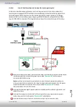
Page 12: ...a connector to the male double Fakra connector of the video interface Disconnect the female double Fakra connector at the head unit s male pink bordeaux coloured Double Fakra connector and connect it...
Page 13: ...ector Connect the picture signal cable s white coloured female Double Fakra connector to the male double Fakra connector of the video interface Disconnect the female double Fakra connector at the head...
Page 14: ...Connect the single black wire of the 10pin Power CAN Cable to stabile vehicle s negative ground Connect the single yellow wire of the 10pin power CAN cable to 12V permanent and stabile power supply Co...
Page 15: ...alogue guide lines can t be shown 2 3 4 1 Connection points CAN all vehicles Attention The two CAN wires may only be connected at the following specified points Tapping the CAN information at other po...
Page 16: ...factory FR7 RVC preparation is only present for Type 1 If the blue single fakra on the head unit is connected for Type 2 If the green double fakra is twice connected on the head unit There s no liabil...
Page 17: ...terminal 86s 12V e g glove compartment illumination Note Only as long as the video interface is switched on via 12V and Manual ACC the MBUX screen is also switched on Otherwise the factory picture is...
Page 18: ...ace receives the reverse gear signal If the interface delivers 12V on the green output wire of the 12pin interface cable while reverse gear is engaged the video interface will automatically switch to...
Page 19: ...elay Disconnect the green cable s preconnected male and female connectors of the 12pin interface cable and connect the green input cable Reverse IN to the output connector 87 of the relay Note Last bu...
Page 20: ...nt camera by keypad short press Dip 1 OFF 12V max 3A simulated ACC while CAN has activity 2 3 6 1 After market front camera The red power supply output ACC front cam out 12V max 3A can be used to powe...
Page 21: ...erface and external keypad Connect the female 4pin connector of the keypad to the male 4pin connector of the 12pin interface cable Note Even if switching through several video sources by the keypad mi...
Page 22: ...ue to changes in the production of the vehicle manufacturer there s always a possibility of incompatibility Connect the 12pin interface cable s female 12pin connector to the male 12pin connector of th...
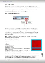
Page 23: ...side in the housing to avoid accidental changes during or after the installation Picture settings must be done separately for all video inputs while the corresponding input is selected and visible on...
Page 24: ...ong press will switch to the next enabled input Inputs which are not enabled will be skipped Note The interface switches after releasing the switch after long pressure Short press of keypad only if DI...
Page 25: ...ether order of LVDS cables is exactly connected according to manual Plugging into head unit does not work when the manual says to plug into monitor and vice versa Wrong monitor settings of video inter...
Page 26: ...y OEM button CAN bus interface does not support this function for vehicle Use external keypad or cut white wire of 6pin to 8pin cable and apply 12V impulses for AV switching Pressed too short For vide...