


Version 21.10.2022
HW: 25(V21)
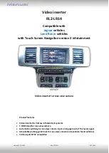
RL2-LR14
P
a
g
e
11
2.5.2.
Case 2: Interface does not receive the reverse gear signal
Connect the blue coloured input cable
“Reverse-IN”
to the output connector (87) of
the relay.
Note: The grey coloured output-cable
“Reverse-OUT”
remains disconnected as it’s
out of function.
Connect the Reverse light’s power-cable to coil (85) and the vehicle’s ground to coil
(86) of the relay.
Connect the output connector (87) of the relay to the rear-view camera’s power-
cable, like you did it to the blue coloured
“Reverse-IN”
cable before.
Connect stabile and per12V to the relay’s input connector (30).
Note: BEFORE completing the installation, check that the switchover to the rear-view
camera takes place by ap12V current to the blue coloured
"Reverse-IN"
wire.


