background image

11

Installation

Adjustment of the Slide Position on the Monitor

Due to transportation, the image position might shift from
the factory setting.  To correct the shift:

1. Remove the two plugs as shown in the figure below.

2. Using a Phillips screw driver, rotate screw #1 to adjust

the vertical position and screw #2 to adjust the horizon-
tal position.

3. Replace the hole plugs.

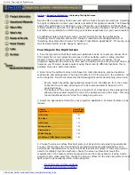
Understanding Which Video Output is Best for You

Y/C (also known as S-video and S-VHS)
Improved resolution that is less grainy due to the elimina-
tion of dot crawl.  Better for presentation of text and
graphic slides, since words are more defined.

Digital (XGA)
True digital output produces more genuine color represen-
tation and even sharper text and graphic images.  XGA
resolution (1024 x 768) is compatible with computers,
LCD projectors and plasma displays. Output available
from the Digital Imaging Station box.

Digital IEEE 1394 (Fire Wire)
This digital output is available directly from the projector
base.  For connection to display devices that accept Fire
Wire input, it is not necessary to use the Digital Imaging
Station box.

Summary of Contents for VideoMate 6100

Page 1: ...VIDEOMATE 6100 Video Slide Projector Instruction Manual The World Leader in Image Quality...

Page 2: ......

Page 3: ...he VideoMate 6 System Diagrams 8 Safety Precautions 9 Quick Start 10 Installation 12 Slide Tray 14 Projection Lamps 16 Features and Functions 18 Camera Operation 19 Digital Imaging Station 22 Troubles...

Page 4: ...uce high resolution images with outstanding contrast and vivid color rendition so slides can be shown as large projected video images without losing clarity or legibility VideoMates are ideal for use...

Page 5: ...5 VideoMate Slide to Video Introduction to the VideoMate Output to Video Equipment Digital Imaging Station...

Page 6: ...6 System Diagrams Top View Side View...

Page 7: ...7 System Diagrams Front View Rear View...

Page 8: ...evere internal damage to the camera and electronics There are no user serviceable components other than changing the lamp Opening the unit will expose danger ous voltage levels and sensitive electroni...

Page 9: ...ad the slide tray onto the projector 4 Turn the TV monitor on and set the VideoMate power switch to HIGH 5 Select a relatively white slide to represent the highest signal level the electronics must ac...

Page 10: ...cessary The goal is to reach a compromise position 6 Adjust the focus F to produce a clear image NOTE Opening the iris will decrease depth of field This means that the darker slides you will open the...

Page 11: ...nd S VHS Improved resolution that is less grainy due to the elimina tion of dot crawl Better for presentation of text and graphic slides since words are more defined Digital XGA True digital output pr...

Page 12: ...tip marker rather than labels that will be loosened by the heat 3 Make sure that the bottom metal plate on the slide tray is indexed into the zero position the plate will not rotate with respect to th...

Page 13: ...ide should come up If the tray is still jammed 1 While holding the projector post release tab located at the center of the slide tray grasp the tray on the side opposite the index mark and lift When t...

Page 14: ...ra tion which may be removed from the projector to change the lamp Unfortunately it takes 5 to 10 minutes to change the lamp because it must first be allowed to cool down Therefore if timing is critic...

Page 15: ...latch of the lamp module and pull it slowly outward until the module clears the projector 4 Unclasp the wire bail which holds the lamp in place and push from underneath the lamp to slide the lamp out...

Page 16: ...ave a rating of no more than 30 V rms and must comply with Underwriters Laboratories Inc low voltage limited energy circuit requirements 8 Pin Contact Data 1 and 3 Zero Position Switch Connects to an...

Page 17: ...d 8 Forward Tray Cycle Connects to the forward tray advance circuitry in the projector These contacts are connected internally to the remote accessory receptacle and an electrical connection made at e...

Page 18: ...ing Station offers many other useful functions For a complete description of camera functions see the enclosed Digital Imaging Station CD ROM A Copy of the Digital Imaging System CD ROM is included wi...

Page 19: ...E 4 Trigger Input Connector Connect the optional RM 91 trigger switch or FS 20 foot switch to input external trigger signals 5 Camera 1 2 3 Input Connectors 6 pin Conform to the IEEE 1394 format 6 PC...

Page 20: ...S Video input connector of a TV monitor 5 NTSC PAL Selector Set according to the color system of the connected TV monitor After changing the position turn off the power and turn it on again 6 XGA Outp...

Page 21: ...g diagram shows an example of the system configuration using the DFSW 77 1 Multiscan PC Monitor 2 TV Monitor 3 Network LAN 4 VideoMate 6100 or Camera 5 Computer 6 Keyboard 7 PC Card 8 PC Card Reader 9...

Page 22: ...e h T n w o l b p m a l e h t s I w o l b o t p m a l e h t d e s u a c e v a h y a m n w o d h s u P n o i t i s o p d e s o l c e h t n i k c u t s r e t t u h s e t a g e h t s I t i e s a e l e r...

Page 23: ...o v 0 2 1 p m a L r o t c e j o r P J S E E G t t a w 5 8 t l o v 2 8 r o t c e j o r P e d i l S E I I I c i h p a r g a t k E k a d o K d e i f i d o M s n e L m m 5 3 8 1 s l o r t n o C s u c o F...

Page 24: ...ther improper servicing or modification by someone other than Navitar Further this warranty does not cover any routine maintenance work that is reasonably expected to be performed by the purchaser No...

Page 25: ...25 Ektagraphic and Kodak are both trademarks of the Eastman Kodak Company VideoMate and Navitar are both trademarks of Navitar Inc Notes...

Page 26: ...Navitar Inc 200 Commerce Drive Rochester NY 14623 USA Phone 585 359 4000 Fax 585 359 4999 Internet http navitar com Email info navitar com...

Reviews: