background image

NAVIS NavDP 4000. Operation Manual

– wait for “Operation ‘Unmount removable drive’ completed successfully” message.
– disconnect USB flash drive from USB port.
– press “Close” button.

2.3. To start

NAVIS NavDP 4000

press “Start DP” button (see Section 3.1, page 50).

2.4. To shut down

NAVIS NavDP 4000

use a normal shut down procedure (see Section 3.6, page 55).

G.2.4

Creating Feedback Package

2.1. Switch DP/IJ control computer into “Service Mode” (see Section G.2.2, page 311).

2.2. Press “Feedback” item in “Services” menu.

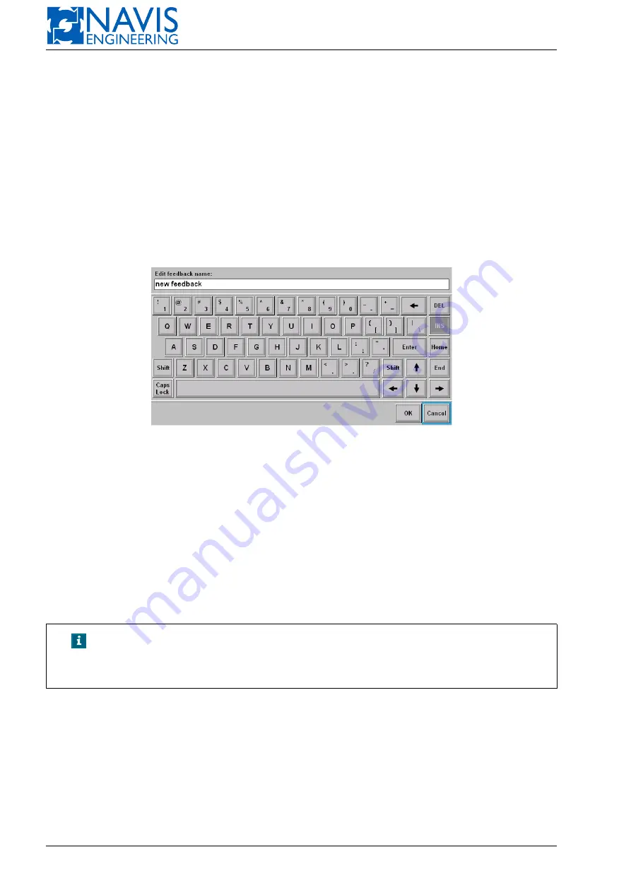
2.3. In “Feedback List” window press “Create New Feedback” item (use arrow buttons for navigation).

Figure G.16: DPShell. Creating feedback

2.4. In “Edit feedback name” window (see Figure G.16):

2.4.1 Change feedback name using a screen keyboard (default name is “new feedback”).

2.4.2 Press“OK” button.

2.5. Wait for “Operation ‘Add feedback to archive’ completed successfully” message.

2.6. Press “Close” button.

2.7. Next, if feedback package was created successfully

DPShell

suggests you to copy feedbacks to USB flash drive. If

you don’t want to copy feedback right now just press “Cancel” button, otherwise you should make sure that USB
flash drive is connected and act the same manner as in section G.2.5, page 313, item 2.5.3.

NOTE!

“Description” field in “Feedback List” window may contain additional
description of the feedback package (for example, “Automatically cre-
ated Feedback”). Editing of this field is unavailable.

G.2.5

Copying Feedback Package to USB Flash Drive

2.1. Switch DP/IJ control computer into “Service Mode” (see Section G.2.2, page 311).

2.2. Insert USB flash drive into DP/IJ control computer USB port.

2.3. Wait for item “Unmount USB” will turn red.

2.4. Press “Feedback” item in “Services” menu

2.5. In “Feedback List” window:

313

Doc. 000.JDP-10000-OME, rev.3.3.13/“2102.$–17A-Advanced”

Summary of Contents for NavDP 4000 Series

Page 1: ...000 JDP 10000 OME NAVIS NavDP 4000 Dynamic Positioning Independent Joystick Control System Operation Manual Software version 3 3 13 2102 17A Advanced Document build 9203 May 2018...

Page 2: ...tures EA TM OK 3 3 10 2015 1600 Release 15A software features EA OK AL 3 3 11 2016 1828 Release 16A software features EA AL LP VS 3 3 12 2017 2100 Release 17A software features Capability analysis ref...

Page 3: ...System 22 2 1 3 IJ mode IJ Control System 22 2 1 4 Autopilot mode 22 2 1 5 Mode Selectors for NAVIS NavDP 4011 or NAVIS NavDP 4022 22 2 2 Operator Stations 23 2 3 Main and Portable Control Panels MCP...

Page 4: ...42 2 7 2 Communication Icon 42 2 7 3 Rotary Knob 42 2 7 4 In Control 42 2 7 5 DIM Mode 42 2 7 6 CANCEL 43 2 7 7 Alarm ACK 43 2 7 8 AutoHDG 43 2 7 9 AutoPOS 43 2 8 Joystick and Rotary Knob 45 2 9 Prin...

Page 5: ...fset heading input 80 5 6 3 Heading new setpoint indication on Map 80 5 7 Enter Crab Angle 81 5 8 Trend View Window 81 5 8 1 Trend View Settings 82 5 9 System Parameters 85 5 9 1 Parameter Pages 85 5...

Page 6: ...red Sensor Indicator 129 7 2 8 Sensors Raw and Used Data Table 129 7 2 9 Data Processing Results 130 7 2 10 Priority Setting 130 7 3 Sensors Details 130 7 3 1 Gyro Sensor Details 131 7 3 2 Wind Sensor...

Page 7: ...tion 189 10 6 2 Track Following Strategy 189 10 6 3 Track Window 190 10 7 Autopilot Function 201 10 7 1 Dodge mode 203 10 7 2 Automatic Speed Control function 204 10 7 3 Manual position 204 10 7 4 Ste...

Page 8: ...enu on the Control Panel of DP IJ Station 311 G 2 3 Leaving the Service Menu on DP IJ Control Station 312 G 2 4 Creating Feedback Package 313 G 2 5 Copying Feedback Package to USB Flash Drive 313 G 2...

Page 9: ...342 J Error Codes 343 J 1 General 343 J 2 CC Error codes 343 J 3 PLC Error codes 343 J 4 Examples 344 K The Trend View Diagrams List 345 K 1 Data Classes 345 K 2 Data Groups and Items 345 K 2 1 Power...

Page 10: ...Reference HS Track High Speed Track HSC Heading Control System I O Input Output IJ Independent Joystick JB Junction Box JDP Joystick Dynamic Positioning LCD Liquid Crystal Display LED Light emitting...

Page 11: ...ensor and manual inputs The manual input position and heading settings is available in any mode To provide the specified moving the set of control signals rpm pitch or azimuth angles etc for every thr...

Page 12: ...NAVIS NavDP 4000 Operation Manual Figure 1 1 NAVIS NavDP 4000 principles 11 Doc 000 JDP 10000 OME rev 3 3 13 2102 17A Advanced...

Page 13: ...sition heading and speed A lot of parameters such as vessel mass draft hull form propulsion type and arrangement superstructure and location etc are used in the model 1 2 2 Wind Model A wind model is...

Page 14: ...VIS NavDP 4000 system provides the vessel moving according to the operators commands and selected mode The Set Point Algorithm transforms operator commands to detailed instructions to Optimal Controll...

Page 15: ...into actual control commands for actuators with the actual power and individual thruster rpm angle etc limits taken into account The commands for thrusters represented in terms of rpm and rudder angle...

Page 16: ...ntrol Station NAVIS NavDP 4001 IJ Control Station Dual redundant DP system with integrated joystick system DP 2 NAVIS NavDP 4022 DP Control Station NAVIS NavDP 4002 IJ Control Station Class DP 0 Syste...

Page 17: ...System Hardware Configuration Figure 2 1 Typical NAVIS NavDP 4000 for DP 0 Class Ship Hardware Configuration Doc 000 JDP 10000 OME rev 3 3 13 2102 17A Advanced 16...

Page 18: ...R 1 All sensors are connected to the DP Control Unit via the DP Operator station junction box Some of them e g Gyro DGPS Wind are also connected to the I Control Unit via the IJ operator station junct...

Page 19: ...System Hardware Configuration Figure 2 2 Typical NAVIS NavDP 4000 for DP 1 Class Ship Hardware Configuration Doc 000 JDP 10000 OME rev 3 3 13 2102 17A Advanced 18...

Page 20: ...NAVIS NavDP 4022 is designed so that no single failure of any unit should result in case of loss of the remaining equipment s ability to maintain a vessel position The NAVIS NavDP 4000 typical hardwar...

Page 21: ...System Hardware Configuration Figure 2 3 Typical NAVIS NavDP 4000 for DP 2 Class Ship Hardware Configuration Doc 000 JDP 10000 OME rev 3 3 13 2102 17A Advanced 20...

Page 22: ...ninterruptible Power Sup ply Unit UPS DP IJ DPA DPB IJ Local Input Ouput Units Operator Station Control Computer DP IJ DPA DPB IJ LCD with Touchscreen DP IJ DPA DPB IJ Junction Box DP IJ DPA DPB IJ Ma...

Page 23: ...tem failed Auto manual heading control modes manual position control modes are available in this mode 2 1 4 Autopilot mode Auto heading high speed track control modes are available in this mode See Se...

Page 24: ...vessel behavior Control Computer The Main Control Panel MCP is used for controlling the vessel manually by means of the joystick and rotary knob alarm acknowledging control transfer and controlling t...

Page 25: ...tting DP system parameters LED Indication Volume control of sound and voice alarms Displaying DP system info on built in color LCD for a model with LCD Control transfer between Control Panels WARNING...

Page 26: ...ee Section 5 12 page 90 Figure 2 7 Control Panel Controls Buttons and Indicators MCP and PCP Disconnected Panel In case the panel has no signal from the system the status is Disconnected In this state...

Page 27: ...E button GiveTake Mode This configuration means that the system should be switched to the transfer state Press the TAKE GIVE button on the active panel NOTE When the TAKE GIVE button is pressed on the...

Page 28: ...ing the HDG push button then pressing the Hold pushbutton In this case the current heading is get as the preset one The pushbutton backlight changes to green To set the heading different from the curr...

Page 29: ...hbutton with the rotary knob see Figure 2 12 turn the knob until the required value of the Sway or Surge parameters is set Then press the Enter pusbutton Press the knob s pushbutton to switch between...

Page 30: ...e Joystick Match indicator hints directions to tilt the joystick It helps to avoid an undesirable jump in the thruster control The Joystick Match indicator shows in which direction the joystick is to...

Page 31: ...utton is red blinked When holding the button the Silence mode is on in case at least one alarm to acknowledge is in list In the Silence mode the button is red non blinking if unaknowledged alarms are...

Page 32: ...the pushbutton to switch to the next window Press on the pushbutton twice to display the list of windows see Figure 2 14 Figure 2 14 List of Windows To switch between the items use the knob rotation...

Page 33: ...ol Panel MCP4000 3 The following components of the Control Panel are mounted on an aluminum base plate Rotary Knob PCB with integrated indicators and electronic components The arrangement of controls...

Page 34: ...e Highlighting means that the vessel is under the system control 2 5 3 TAKE GIVE The TAKE GIVE button is used for transferring control between DP A and DP B systems for DP 2 systems control panels of...

Page 35: ...rring state automatically In case of emer gency outage of a portable control panel the control is transferred to the main control panel automatically 2 5 4 Communication indicates the control panel co...

Page 36: ...The arrow buttons see Figure 2 21 are meant for the knob match indication position and heading offset 2 5 10 HDG The HDG pushbutton can be used in the DP IJ and Autopilot modes to select Auto Heading...

Page 37: ...t necessary value then press the Enter pushbutton Figure 2 22 Knob Match Figure 2 23 Rotary Knob NOTE The HDG settings dialog is called in any control mode by the single pressing the HDG pushbutton To...

Page 38: ...ol mode by single press ing the POS pushbutton To switch off the AutoPOS mode press the POS pushbutton twice 2 5 12 HOLD The HOLD button is used to take actual position and or heading as preset ones f...

Page 39: ...System Hardware Configuration Figure 2 24 Control Panel Controls Buttons and Indicators MCP and PCP Figure 2 25 Portable Control Panel Doc 000 JDP 10000 OME rev 3 3 13 2102 17A Advanced 38...

Page 40: ...TE In case of emergency outage of a main control panel the system is switched to the control transferring state automatically In case of emer gency outage of a portable control panel the control is tr...

Page 41: ...is selected the knob is used for generating the control moment in the yaw axis which is proportional to the angle of the knob rotation 2 6 11 Joystick Position In the Manual Position Control Mode the...

Page 42: ...utton is available in the DP mode only and it s meant for selecting the Auto Position control mode The button responds to double click to prevent an accident operation Upon double click an actual posi...

Page 43: ...t the top bottom left right rotary handle Rotary knob is meant for position and heading offset menu navigation set parameters in Quick settings menu controls navigation 2 7 4 In Control The In Control...

Page 44: ...NOTE The HDG settings dialog is called in any control mode by the single pressing the AutoHDG pushbutton To switch off the AutoHDG mode press the AutoHDG pushbutton twice 2 7 9 AutoPOS The AutoPOS pus...

Page 45: ...enu is open by pressing the button Menu The following settings are available see Figure 2 31 Audio volume Press knob In the opened dialog window change the volume by rotating knob see Figure 2 32 Pale...

Page 46: ...les Before operating the joystick the Joystick Gain value should be checked Figure 2 34 The Joystick Gain determines the ratio of joystick tilt angle to the force value as well as of the knob rotation...

Page 47: ...System Hardware Configuration Figure 2 35 Joystick limits and gain types Figure 2 36 NAVIS NavDP 4000 speed designation rules Doc 000 JDP 10000 OME rev 3 3 13 2102 17A Advanced 46...

Page 48: ...37 Epson LX 300 Figure 2 38 Epson LX 350 The alarm printer is connected to the control computer via serial COM Port RS 232 The printer status is displayed with round indicators in the System monitor...

Page 49: ...nd indicators in the System Monitor window see Figure 2 39 green the printer is available red the printer is not available Forced alarm printing is possible on this printer For forced printing press t...

Page 50: ...ndicators in the System Monitor window similar to the alarm printer status see Figure 2 39 green the printer is available red the printer is not available Print screen For MCP2000 and MCP4000 3 famili...

Page 51: ...ontrol Unit Before pressing this pushbutton make sure about the position of the Mode Selector To switch the DP system ON first set the Mode Selector to the OFF Manual position See Figure 2 4 3 1 2 Pow...

Page 52: ...ces Shut Down Select Shut Down if you are going to switch the control system off In case there is no any work station the system will shut down In case the system has several work stations the followi...

Page 53: ...ching On Off and Troubleshooting Figure 3 3 The Shut Down menu of an associated work station Figure 3 4 The Shut Down menu of an separate work station Doc 000 JDP 10000 OME rev 3 3 13 2102 17A Advance...

Page 54: ...re 3 5 Service menu listing If you select Real Mode the control system gets ready to take control over the thrusters and immediately checking the interfaces with the sensors position reference systems...

Page 55: ...Switching On Off and Troubleshooting Figure 3 6 Starter menu Versions subwindow Figure 3 7 Starter menu Versions subwindow details Doc 000 JDP 10000 OME rev 3 3 13 2102 17A Advanced 54...

Page 56: ...that press and hold for two seconds the Take Control button on the Main Control Panel of the slave system If the Portable Control Panel is connected to the control system you can transfer control in t...

Page 57: ...ching off System for the DP system closing Press the symbol at the menu title to back to the main screen NOTE The switching off process for multi WS configuration is described in the Section 3 2 page...

Page 58: ...he Alarm Window Messages may be new not acknowledged and actual alarm condition is presented or not actual Some events cannot be actual like information messages for example Gyro filter started NOTE F...

Page 59: ...y to acknowledge all the messages displayed in the window Use arrow softkeys to select a message The selected message is displayed against blue background Press All softkey to display all the messages...

Page 60: ...NAVIS NavDP 4000 Operation Manual Figure 4 3 Alarm List Window Figure 4 4 Alarm Details 59 Doc 000 JDP 10000 OME rev 3 3 13 2102 17A Advanced...

Page 61: ...wing format The message in dicator Act the mes sage status if the alarm is active or not and the sys tem the alarm be longs to see the sections below Date the date of message initi ated Time the time...

Page 62: ...d is set in the Alarm Page Printing field by chosing one of hte following values 10 min 30 min 1 h 2 h 3 h 4 h 6 h 12 h 24 h In case Off value is set the alarm page is printed after it has been totall...

Page 63: ...alarm is acknowledged the alarm is not acknowledged Column 5 control station ID Possible values are A the alarm is active on CCA B the alarm is active on CCB AB the alarm is active both on CCA and CC...

Page 64: ...e applicable for the wide screens with resolution 1680x1050 1920x1200 etc Screen with two standard windows and additional left console see Figure 5 3 The additional left console contains the same area...

Page 65: ...Operator Interface Figure 5 2 Example of the Operator Interface Screen Figure 5 3 The Wide Screen Layout with Additional Left Console Doc 000 JDP 10000 OME rev 3 3 13 2102 17A Advanced 64...

Page 66: ...S NavDP 4000 Operation Manual Figure 5 4 Example of the Wide Screen with Additional Left Console Figure 5 5 The Wide Screen Layout with Three Windows 65 Doc 000 JDP 10000 OME rev 3 3 13 2102 17A Advan...

Page 67: ...ss the exit softkey operating in the DP mode for DP station and operating in the IJ mode for IJ station See Section 3 6 page 55 for details 5 1 2 Alarm Message Line The Alarm Message Line displays the...

Page 68: ...section 7 page 126 REF Reference System Window section 8 page 139 Target Target Window section 10 5 page 180 Track Track Window section 10 6 3 page 190 CAP Analysis Capability Analysis Window Drift A...

Page 69: ...he screen with two win dows b For the screen with three windows Figure 5 8 Select Window Examples Figure 5 9 Status and Alarm Message Lines Figure 5 10 Quick Switcher Panel Doc 000 JDP 10000 OME rev 3...

Page 70: ...NAVIS NavDP 4000 system Softkey is used to open home page of the Help window Home page contains a list of all Manual sections as hyperlinks see Figure 5 11 and Softkeys are used for navigation between...

Page 71: ...ndow Manual Thruster Section Manual Thruster Window 5 4 Position and Heading Display Map View The Map window Figure 5 13 contains the vessel s position and heading information The information represen...

Page 72: ...NAVIS NavDP 4000 Operation Manual Figure 5 13 Display example 71 Doc 000 JDP 10000 OME rev 3 3 13 2102 17A Advanced...

Page 73: ...de 5 4 2 Vessel position displaying Position Error Auto Position Mode Indicators display the deviation of a vessel from Set Position The left Position Error indicator displays the deviation in the sur...

Page 74: ...ass moving with current speed within 1 minute The COR position is set by the operator in DP modes See Section 10 1 page 171 Position setpoint symbol If the vessel position is controlled automatically...

Page 75: ...screen Figure 5 14 Trace Points Example The vessel trace is shown on the screen according to Step and History settings for the vessel trace These settings are made by the operator in View page of Par...

Page 76: ...e in the Param window tab View see fig 5 16 In case the Motion prediction is on the yellow vessel outline is displayed at the position calculated for given time the time settings are 30 sec 1 min 2 mi...

Page 77: ...epend on the current control mode In case of the manual position control the current coordinates are displayed In case of the auto control the latest position setpoint is displayed Figure 5 18 Input P...

Page 78: ...te system The current offset value can overflow the reserved digits In this case the entry field will be red and the symbols will be displayed see figure 5 20 Select the first coordinate system and en...

Page 79: ...Operator Interface Figure 5 20 The field overflow Figure 5 21 Position new setpoint indication on Map Doc 000 JDP 10000 OME rev 3 3 13 2102 17A Advanced 78...

Page 80: ...ing setpoint difference between the actual heading and this one setpoint P symbol means that the rotation direction is to the left from the actual heading to the set one S to the right respectively DE...

Page 81: ...d to check the New Deviation Direction when entering an offset value When operator press Hold button dialog is switched to preset heading input mode Offset button is off 5 6 3 Heading new setpoint ind...

Page 82: ...blocks that graphiclly display trends of three independent parameters selected by operator A trend period is defined by operator too and it is the only one for the all trends Each block has several mo...

Page 83: ...ailable by clicking on the diagram background area see Figure 5 27 The settings console contains three blocks Data Type to chose the data type Y axis values setting Time axis time interval setting Fig...

Page 84: ...n selected the class selection console switches to the settings one with the selected class name displayed near the Class button see Figure 5 29 Figure 5 29 The current class name displayed on the set...

Page 85: ...clicking the Angle button 5 8 1 3 Time axis There are two modes to display a trend Actual and History NOTE All time settings are general for all trends It means that whenever changes occur all trends...

Page 86: ...Parameters HDG DP Heading Parameters POSN Position Parameters COR COR Point Edit AP Autopilot Parameters View View Parameters Units Measure Units COORD Coordinate Systems Parameters THR LIM Thrust Lim...

Page 87: ...Operator Interface Figure 5 33 Light Theme Figure 5 34 Classic Theme Doc 000 JDP 10000 OME rev 3 3 13 2102 17A Advanced 86...

Page 88: ...NAVIS NavDP 4000 Operation Manual Figure 5 35 Dark Theme 87 Doc 000 JDP 10000 OME rev 3 3 13 2102 17A Advanced...

Page 89: ...l keyboard For instance Press the Set softkey keyboard like dialog will appear Using softkeys move the blue cursor and print digits on its place Then press the Ok softkey to confirm or the Cancel soft...

Page 90: ...System tab see figure 5 37 After the value has been changed press the Apply softkey to switch the mode or Cancel softkey to hold on the current one Switching the Mode via Icon The mode switching is av...

Page 91: ...rator selected GPS operates normally data from the sensor are used by the system In case the sensor is not used or failed the following alarm is generated Selected GPS for Time Auto Synchronize was tu...

Page 92: ...NAVIS NavDP 4000 Operation Manual Figure 5 40 LCD Panel Figure 5 41 The Screen Operational Areas Layout 91 Doc 000 JDP 10000 OME rev 3 3 13 2102 17A Advanced...

Page 93: ...ssage is displayed in the top alarm bar 5 12 1 2 Auto Pilot View Operating in the autopilot mode AP main view contains the following information see Figure 5 42 The current heading The heading set The...

Page 94: ...jump between the sensors buttons use the encoder The selected buttons is yellow frame indicated Figure 5 44 Sensors View 5 12 1 4 Thrusters View The view contains the list of the thrusters see Figure...

Page 95: ...ated with yellow frame Figure 5 46 REF View 5 12 1 6 Power View The view displays the vessel power system scheme the power distribution and general power consumption see Figure 5 47 Figure 5 47 Power...

Page 96: ...sensor system is in use in the monitoring mode gray sensor system is not in use red sensor system is in use data is not valid For thrusters and propellers green thruster propeller is running in normal...

Page 97: ...ding Console 5 12 4 2 Position Console The SOG and COG values a displayed in the console Additionaly operating in DP mode In the AutoPos mode the console contains the graphic view in relative coordina...

Page 98: ...anual Figure 5 51 Position Console Figure 5 52 Position Console in the POS Mode Figure 5 53 Position Console in the Hold Area Mode Figure 5 54 Position Console in the AP Mode 97 Doc 000 JDP 10000 OME...

Page 99: ...the Mode Selector is in the Off position In other cases the status bar indicates the following data Control mode DP AP IJ Heading mode AUTO MAN Target LS Track Min Power Dodge Position mode AUTO MAN H...

Page 100: ...from available in a list Service switch to the Service menu NOTE The item list depends on the system configuration The Service menu RETURN back to the previous window Set panel role the panel role set...

Page 101: ...der The HDG dialog is activated in similar way pushing the HDG button or a Knob Match indicator The control is provided by the Knob Match indicators As for the POS dialog the control is delegated to t...

Page 102: ...o Thruster Window The Thrusters View is displayed at the bottom of the Auto Thruster Window The Thrusters State Table is displayed at the top of the Manual Thruster Window The Manual Thrusters Control...

Page 103: ...disturb possible combinations of the forces vector F and moment M The Thrust Ability Diagram works in terms of forces vector F and moment M and is based on the Thruster Allocation Function usage see S...

Page 104: ...ea for thrust F are of maximum size if maximum power from diesels or generators is provided to the thrusters all the thrusters are included in the Auto Thruster Group all the limits in the Thruster Pa...

Page 105: ...Fcontrol and moment Mcontrol The green vector and bar mean the actual force and moment respectively Digital indicators show the components of X Y and M in to required force maximal values and force va...

Page 106: ...direction is the same as syncronization Figure 6 4 Thrust Ability Diagram Red arrows need to synchronize The system keeps the actual value of force till the synchronization and moment and doesn t rea...

Page 107: ...red otherwise it is not shown at all The indicator shows whether the situation is normal or faulty See failure section 6 2 4 3 page 114 for details 6 1 3 5 Mode Indicator Mode indicator is text indica...

Page 108: ...maximum The following notation is used AS means astern AH means ahead Figure 6 7 Propeller Bar Graph Figure 6 8 Propeller Numerical Display 6 1 4 3 Azimuth Thruster The Manual Thruster window include...

Page 109: ...it leaves the nozzle This reverses the direction of the force generated by the jet stream forward and down to keep the boat stationary or propel it in the astern direction The Manual Thruster Window c...

Page 110: ...his thruster Figure 6 16 Propeller bar graph The thrust is given in to maximum 6 1 5 3 Azimuth Thruster For this thruster NAVIS NavDP 4000 controls the thrust direction azimuth as well as the thrust i...

Page 111: ...tual thrust yellow as well as the thrust required green Pointer shows the thrust limit which has been set in the Thrust Page for this thruster Figure 6 21 Tunnel thruster bargraph and shows the requir...

Page 112: ...s Dealing with a thruster NAVIS NavDP 4000 operates in term of its thrust in whatever way the thrust is produced NAVIS NavDP 4000 receives feedback signals rpm pitch azimuth angle rudder angle etc and...

Page 113: ...softkeys can be used in Manual Thruster window to control the thruster These softkeys are light green When pressing these softkeys the thrust demand the green line can be changed The thruster control...

Page 114: ...signals clutch ahead astern feedback signals for propellers port starboard feed back signals for tunnel thrusters Thruster CB Status Discrete feedback signal from a thruster open close for PMS functio...

Page 115: ...colored red In this situation the thruster is not available for DP and the thruster control softkey is grey in whatever position the Mode Selector is set Since the thruster can later be available for...

Page 116: ...ER softkey The new thruster s state is Run Select Ready Fault Green Green Red Red If the waiting period of time expires but there still is no READY signal the thruster s state changes to the previous...

Page 117: ...orks ahead Stbd Ahead TAL Mode for twin propeller FPP ship Starboard propeller works ahead Low Bias Low degree of thruster bias About thruster biasing see below High Bias High degree of thruster bias...

Page 118: ...NavDP 4000 Operation Manual Figure 6 29 Thrust Allocation Modes Starboard Ahead and Port Ahead Figure 6 30 Thrust Allocation Modes High and Low Bias 117 Doc 000 JDP 10000 OME rev 3 3 13 2102 17A Adva...

Page 119: ...Figure 6 32 PMS Function Turning On Off In case PMS monitor function is turned off by the operator the red colored text PMS Function Off is displayed on the Master CPU panel see Figure 6 33 Figure 6...

Page 120: ...Engine Overload Protection functions can be turned on off from PARAM window PWR LIM tab see Figure 6 34 Figure 6 34 Overload Protection Settings In case generator engine overload protection is turned...

Page 121: ...own how generators and thrusters are connected to buses power produced by each generator power consumed by each thruster status of each circuit breaker and tie breaker how extra load if any such as Fi...

Page 122: ...signal from the DP control system This limit is set in Power Limits page of Param window Pointer shows the power limit which has been set in the Param window If the diesel engine can run a FiFi pump i...

Page 123: ...r Limits page of Param window and shown with pointer Main Engine The information about the power consumed by the main engine is displayed as shown in Figure 6 42 Figure 6 42 Main engine on scheme whic...

Page 124: ...uipment may be for instance the vessel s power management system If this signal has come the thruster command signal is limited by the external equipment so that it may be the feedback signal differs...

Page 125: ...layed as a percentage of the maximum available power on a bar graph Dark blue bar shows the power used for DP operations Light blue bar shows the power consumed by the external power consumers Numeric...

Page 126: ...r thruster There may be two situations where the generator circuit breaker status signal and the generator power signal are mutually contradictory the circuit breaker is open while the generator power...

Page 127: ...S sensors Two alarm levels are used alarm only with changing the priority sensor and reject sensor Discrepancy test for two sensors alarm only Prediction test alarm when raw data and fiter output disc...

Page 128: ...is white colored The others are grey colored Arrow softkeys Use the arrow softkeys to scroll a list of sensors if required in case many sensors of different groups are used The softkeys are light grey...

Page 129: ...ter indicator and Preferred sensor indicator Figure 7 3 Figure 7 3 Sensor softkey with indicators 7 2 4 Sensor Softkey A sensor s name is the title of the proper sensor softkey Use the sensor softkey...

Page 130: ...l the strokes merge into one line The color of a single stroke provides you with the information about the corresponding piece of data Green the data received from the sensor have a correct structure...

Page 131: ...y appears in two minutes and the indicator becomes grey The filter does not operate When the system starts up and no valid data are received by the sensors the filter is not able to start up The alarm...

Page 132: ...ral view of the top of the Gyro window for three gyrocompasses is shown in Figure 7 6 Figure 7 6 Gyro Details Processing results Vessel heading Yaw rate BIAS is to provide a continuous estimation of h...

Page 133: ...e 7 9 Gyro Trend view In case of loosing good data from all of gyrocompasses it means that course filter is not ready NAVIS NavDP 4000 can not use data not only from gyrocompasses but also from refere...

Page 134: ...softkey and Data Filter indicator become red colored 7 3 2 Wind Sensor Details General view of the top of the Wind sensor window is shown in Figure 7 11 Figure 7 11 Wind details Processing results Win...

Page 135: ...wing graphs are provided for VRS Figure 7 15 Pitch angle raw data processing results Roll angle raw data processing results Figure 7 15 VRS Trend view 7 3 4 LOG Details General view of top part of the...

Page 136: ...and loading displacement values Detailed data includes Sensor softkey with indicators Ship contour with marked measurement points if any Draft measurements in specified points raw data if they are me...

Page 137: ...ptionally operator input not draft but loading in tons it is config ured for each system Press Change softkey to show the draft loading input dialog see Figure 7 20 When operator press Ok value of dis...

Page 138: ...sing results Draft raw data processing results Figure 7 22 Draft sensor Graphs 7 3 6 Tension Details 7 3 6 1 Tension detailed data In general tension sensor measures cable pipe other tension force in...

Page 139: ...or Fragment of sensors window Figure 7 24 Tension sensor details Figure 7 25 TS Graph 7 3 6 2 Variable draft and loading graphs The following graphs are provided for tension info see figure 7 25 Force...

Page 140: ...he coordinates in different coordinate systems UTM Coordinates Parameters The following parameters are available from Operator Station False Northing Yes No abscissa origin is displaced by 10 000 000...

Page 141: ...he one specified in the system It s convenient if it s required to enter the known point coordinates i e in map zone different from the current one 8 1 1 Target Offset If the Target mode is available...

Page 142: ...System of MAP View The coordinate system displayed in MAP View on a map is changed with pressing the button Local N E Geo or UTM depending on a current displaying of the coordinate system on View Con...

Page 143: ...Position References Figure 8 5 Map window in UTM mode Figure 8 6 Map window in Local N E mode Doc 000 JDP 10000 OME rev 3 3 13 2102 17A Advanced 142...

Page 144: ...Section 8 8 3 page 148 Ship position and velocity estimation is weighted average of all selected ref systems filtered data The estimated deviation between Origin Ref and each other selected Ref syste...

Page 145: ...parameters drifted ref system will be rejected or alarm generated Variance test reduction of weights in accordance to noise variance Signal droup out test detection of signal drop out and signals red...

Page 146: ...are available for the selected Ref system View status displays information for the selected Ref system View depends on the Ref system type Param status allows changing parameters of the selected Ref s...

Page 147: ...erence Data from the Ref system are being used by NAVIS NavDP 4000 Dark green Data from the Ref system are coming to NAVIS NavDP 4000 sensor is only monitored Red The ref system fault is detected It c...

Page 148: ...key If the transponder is used as mobile marker is shown at plot and an indicator mob appears instead of the marker to the left of the Ref system softkey If the status of transponder data processing i...

Page 149: ...ent dark green Ref system is available and it s not origin at the moment and used by the system Press the dark green Ref system softkey in the abovementioned dialog box to select another Ref system as...

Page 150: ...d Track Mode figure 8 17 Figure 8 17 Dialog box in High Speed Track Mode If you choose Yes System will switch to Auto Heading mode Else ship will jump on a map mode will High Speed Track and track wil...

Page 151: ...re 8 19 Figure 8 19 DGPS View The sensor softkey with indicators and raw data are shown in detail Lat Lon X Y Local N E system Nsat number of satellites HDOP horizontal dilution of precision GPS facto...

Page 152: ...d directions For example if GPS is placed in aft part Ahead coordinate will be negative For the sensor at portboard coordinate STBD is negative Up is calculated from a waterline Weight is a relative w...

Page 153: ...8 8 7 Detailed Information for Hydroacoustic System For each HPR View Param and Plot Graph windows are available 8 8 7 1 HPR View HPR View is shown in figure 8 24 In window with detailed information a...

Page 154: ...NAVIS NavDP 4000 Operation Manual Figure 8 24 HPR View Figure 8 25 HPR Parameters 153 Doc 000 JDP 10000 OME rev 3 3 13 2102 17A Advanced...

Page 155: ...shown in figure 8 27 Figure 8 27 HPR Graph Graphs are shown in this mode HPR measurements X and Y For more information about view settings for graph refer to Section 5 8 page 81 8 8 8 Detailed Inform...

Page 156: ...set analogously to the GPS accuracy 8 8 8 3 LR Plot LR Plot is shown in figure 8 30 Figure 8 30 LR Plot Transponders of the given LR are shown in this window which are used as Ref squares as Tgt rhom...

Page 157: ...and Plot Graph windows are available 8 8 9 1 TW View The view of the window depends on the TW type standard see figure 8 32 or ATW see figure 8 33 Figure 8 32 The standard TW view The following alarm...

Page 158: ...rs displayed vessel outline depressor weight position horizontal projection of the wire from gimbal head to depressor weight boundaries of the zone accessible with the given wire lenght 8 8 9 4 TW Gra...

Page 159: ...Position References Figure 8 35 TW Plot Figure 8 36 TW Graph Figure 8 37 Graph settings dialog Doc 000 JDP 10000 OME rev 3 3 13 2102 17A Advanced 158...

Page 160: ...avDP 4000 Operation Manual TW Beta rightwards angle TW Length wire length For more information about view settings for graph see the Section 5 8 page 81 159 Doc 000 JDP 10000 OME rev 3 3 13 2102 17A A...

Page 161: ...e softkey once again it stops blinking If the softkey is blinking but you are doing nothing the softkey stops blinking after a few seconds If you press the softkey while it is blinking that is your co...

Page 162: ...ust Ability Diagram Following options can be used in this mode Auto Wind Compensation function see Section 10 2 page 173 Remote COR position COR in bow stern or other specified point The vessel motion...

Page 163: ...th any position control mode The rotational moment demand is calculated by the controller During the operation operator can change heading setpoint When changing heading by the control panel s knob th...

Page 164: ...exceeded an alarm is produced See Section 5 6 page 79 for details about enter heading setpoint 9 2 4 Relative Bearing to Target This mode can be activated only if the Target Follow mode is activated...

Page 165: ...mit specifies the ceiling value of rudder offset See Section 10 6 page 189 for details 9 2 6 Heading by Low Speed Track This control mode is available only if the Low Speed Tracking control mode has b...

Page 166: ...rtional to the joystick position It is recommended to initiate the Auto Thruster window to see what amount of the thrust can be produced in each direction The vessel motion in Manual Position mode is...

Page 167: ...tion setpoint value During the operation you can press the AUTO softkey and set a new value for the position setpoint Following options can be used in this mode Position Setpoint Set Position Offset t...

Page 168: ...drive this deviation to zero while the longitudinal vessel s motion is controlled by the joystick the lateral joystick axis is disabled During the operation you can change the position setpoint which...

Page 169: ...e the vessel with the component speeds accordingly to the joystick position If you select Manual you must set exact values for the longitudinal and lateral vessel s component speed setpoints To activa...

Page 170: ...l and the track see Figure 9 13 The vessel heading can be controlled either manually or automatically See Section 10 6 page 189 that describes how to set a track s operate in the Track window and set...

Page 171: ...ging track leg WP Predict Alarm Specifies weather an alarm should be issued when the vessel approaches the waypoint Figure 9 13 Position mode LS Track Control See Section 10 6 page 189 for more inform...

Page 172: ...n for a number of reasons related to the operation currently underway Some examples of changing the COR to the position of a crane wire that is connected subsea so that a change in heading doesn t pul...

Page 173: ...s and how much its speed is exact values for the COR course and speed are displayed at the top of the screen and denoted as COG and SOG consequently If COR is set at the bow or stern the softkey remot...

Page 174: ...en press the AUTO softkey in the POS panel A window appears in which you can see the actual vessel coordinates and set the position setpoint in terms of the COR position selected In this mode the cont...

Page 175: ...System Functions Figure 10 5 AWC function If you acknowledge the AWC softkey becomes dark and the AWC function is not active See Figure 10 6 Doc 000 JDP 10000 OME rev 3 3 13 2102 17A Advanced 174...

Page 176: ...rce demand is calculated as sum of demand depending on joystick position and the force needed to compensate the wind disturbance Fdisturb See figure 10 5 for details You can consider this as a shift i...

Page 177: ...the bow will stay inside the preset sector This function operates in Auto Position and Hold Area if available modes The function is activated by the Min Power softkey After preesing the softkey a dial...

Page 178: ...peration Manual Figure 10 11 The Min Power dialog sector is ON stern direction Figure 10 12 Map Window when the Min Power function is ON and Sector parameter is ON 177 Doc 000 JDP 10000 OME rev 3 3 13...

Page 179: ...area radius Warning Radius of the Hold Area Radius an alarm is generated in case the vessel approach to this radius Stop Radius of the Hold Area Radius the radius of the area where the vessel stops T...

Page 180: ...NAVIS NavDP 4000 Operation Manual Figure 10 14 Hold Area parameters Figure 10 15 Hold Area settings dialog 179 Doc 000 JDP 10000 OME rev 3 3 13 2102 17A Advanced...

Page 181: ...of the Target window The transpon ders are selected as targets or are available to be selected as targets The lower part of the window consists of Target plot Graph Target Processing results Transpon...

Page 182: ...e ID transponder is indicated in the rhomb if it has been selected as target The color of the transponder is the same as the sensor one Transponders selected as position reference systems are not disp...

Page 183: ...in Rel mode Vx Speed on X direction Vy Speed on Y direction In case the MultiTarget mode is activated the following data are displayed Range to Tgt 1 see Figure 10 25 Bearing to Tgt 1 that can be pre...

Page 184: ...et Following mode by pressing TARGET softkey on POS panel TARGET softkey is available if the target processing status indicator is not grey colored Target Following mode is not recommended in case the...

Page 185: ...ch the vessels stops when entering it The target is at the center of this circle Figure 10 20 Reaction Radius Position 1 The ship is outside of the Reaction Radius Watch Circle and moving towards the...

Page 186: ...trying to take these actions the following alarm will be generated Can not change target settings in target following mode Figure 10 22 Map View the relative bearing is to the target In the Figure 10...

Page 187: ...System Functions Figure 10 23 Map View control goal is achieved RR 30m Figure 10 24 Map View control goal is achieved RR 100m Doc 000 JDP 10000 OME rev 3 3 13 2102 17A Advanced 186...

Page 188: ...IS NavDP 4000 Operation Manual Figure 10 25 Multi Target Following Mode Coordinate Systems Figure 10 26 Multi Target Following Mode Basic Principles 187 Doc 000 JDP 10000 OME rev 3 3 13 2102 17A Advan...

Page 189: ...rget softkey see Figure 10 27 Target coordinate system the origin is in the Tgt 1 X axis is directed to Tgt 2 Y axis is perpendicular to Tgt 2 so that the shortest turning from X axis to Y axis will b...

Page 190: ...NAVIS NavDP 4000 starts operation in the track control mode Use Track and Map windows to see how the vessel follows the route 10 6 2 Track Following Strategy In HS Track mode the heading is automatica...

Page 191: ...flash drive load external route by COM Ethernet port and for monitoring the track following Press Select window softkey on the SYS panel for choosing the Track window The top section displays route l...

Page 192: ...ess Set active softkey The window will be switched to the Active mode Press the RT List softkey to switch to the list of routes back Active route row is highlighted with dark red and is not editable s...

Page 193: ...In case the empty route or one point route is selected an empty route is added by default without calling the dialog Edit Route Press Edit Route softkey to switch to RT Edit mode In this mode the foll...

Page 194: ...on Manual Figure 10 32 Protection from the Route Name Duplication a Geo b Realtive c Polar d True Figure 10 33 Add Edit Waypoint Window Figure 10 34 Delete Point Dialog 193 Doc 000 JDP 10000 OME rev 3...

Page 195: ...rameters for the leg if necessary see Figure 10 36 vessel heading waypoint passing strategy radius vessel speed a Heading b Radius c Speed Figure 10 36 Parameter Setting for the Custom Leg To exit fro...

Page 196: ...tive editing is allowed route is overwritten the route is active editing is not allowed the route gets a new name like route name 1 Save A route can be saved to an external device for example USB flas...

Page 197: ...yed on the map in the MAP window but keep in mind that only the waypoints with coordinates inside the visible area are displayed The route is added to the list just after the Load softkey is pressed 1...

Page 198: ...Limit m WP Predict Alarm on off WP Predict Alarm Time if WP predict alarm is on Press Apply softkey if the changes should be applied Cancel if should not or Defaults if the default values should be se...

Page 199: ...everal intermediate ones 10 6 3 4 Waypoint Motion Control Console In case of any Track mode LS Track HS Track is on the bottom section of the window displays the following parameters At the bottom of...

Page 200: ...ack error NOTE For XTE R means X Track Error on Starboard L means X Track Error on Portside DTW distance to waypoint BTW bearing to waypoint BOD bearing origin destination Leg distance from the previo...

Page 201: ...allel parallel offset of the entire track Leg parallel offset of the entire track s segment other points are still fixed Figure 10 46 Offset Dialog Active route is displayed on the Map window by green...

Page 202: ...s see Figure 10 49 The bottom of the Autopilot window contains controls to change the Autopilot parameters see figure 10 50 There are compass rose at the top of the Autopilot window and some additiona...

Page 203: ...System Functions Figure 10 48 Autopilot window example Figure 10 49 Steering System Monitoring Area Figure 10 50 The Autopilot parameters Doc 000 JDP 10000 OME rev 3 3 13 2102 17A Advanced 202...

Page 204: ...tkey it starts blinking If pressed Hold is unconfirmed within 30 sec the preset heading is unchanged and Hold stops to blink Press it once more to cancel or the ENTER softkey to confirm When you press...

Page 205: ...to Dodge 10 7 2 Automatic Speed Control function Automatic Speed Control function is provided as option To turn on this function press Speed softkey Set speed dialog will be activated Figure 10 55 Use...

Page 206: ...h Green bar shows thrust command Yellow bar shows actual thrust Red triangles shows thrust command limits Propeller softkeys See Section 6 2 1 page 111 for status details Steering System Status indica...

Page 207: ...nction is ON there is no off limit discrepancy red the function is ON there is off limit discrepancy light gray the function is OFF there is no monitoring In the DP mode the HM indicator is green in c...

Page 208: ...lity is evaluated with regards to both simulated failures and limitations of thrusters and power components and combinations of waves wind and current Use the Capability Plot to determine operational...

Page 209: ...marker indicates wind direction Cyan marker indicates wave direction It matches the wind direction in Auto mode Electronic Bearing Line EBL EBL Electronic Bearing Line is displayed as lilac line It is...

Page 210: ...DP 4000 Operation Manual a EBL 0 b EBL 30 Figure 10 59 Limiting Wind Speeds for Different EBL Directions Figure 10 60 Dialog Box for EBL Direction Setting 209 Doc 000 JDP 10000 OME rev 3 3 13 2102 17A...

Page 211: ...ility View in Real Mode Thruster and Power Configuration A list of the DP system components thrusters power components bus tie breakers is displayed in the bottom of the Capability Analysis window see...

Page 212: ...color Wind Waves and Current The information about the present environmental conditions wind waves and current is displayed in the right part of the Capability Analysis window The values for current d...

Page 213: ...s thrusters power components bus tie breakers is displayed in the bottom of the Capability Analysis window see Figure 10 63 so that different power and thruster configurations can be analyzed Each com...

Page 214: ...NAVIS NavDP 4000 Operation Manual Figure 10 63 The Capability View in Hypothetic Mode 213 Doc 000 JDP 10000 OME rev 3 3 13 2102 17A Advanced...

Page 215: ...on of Hypothetic Environmental Conditions Wind Waves and Current Current Press Change softkey to set values for the current direction and speed In the opened dialog box see Figure 10 66 select the cur...

Page 216: ...e enter a new value in degrees in the DIR field or press Hold softkey to enter present value for the wind direction press OK softkey to apply the choice and leave the dialog box In case an incorrect v...

Page 217: ...hange softkey for manual input of the wave parameters direction and height In the opened dialog box see Figure 10 68 select the wave direction value enter a new value in degrees in the DIR field or pr...

Page 218: ...ion etc and apply it then the refresh process starts Selection of Hypothetic TAL Mode To select a TAL mode press Change softkey located under the TAL mode name select a desired TAL mode in the opened...

Page 219: ...rrent Figure 10 70 Example of the Capability Plot Printout Hypothetic Mode TRUE view 10 9 Drift Analysis Drift Analysis is performed to predict the vessel s hypothetic drift for set failures and envir...

Page 220: ...Figure 10 71 Drift Plot Drift Plot Drift Plot Softkeys TRUE REL Drift Plot view The Drift Plot is displayed in two views see Figure 10 72 TRUE orientation to the North REL orientation to the vessel s...

Page 221: ...Circle indicates set drift limit Press Change softkey near the Watch Circle Radius text to set a watch circle radius In the opened dialog box enter a new value for the watch circle radius and press O...

Page 222: ...NAVIS NavDP 4000 Operation Manual Figure 10 74 Drift Plot Window 221 Doc 000 JDP 10000 OME rev 3 3 13 2102 17A Advanced...

Page 223: ...ted Each component can be activated and deactivated Round indicator shows status of each component Green color means for the thruster it is activated for the power component it is activated for bus ti...

Page 224: ...softkey is unavailable Press Cancel to leave the dialog box without any changes Figure 10 76 Example of the Dialog Box for Editing the Thrust Power Limits When the tie breaker is selected On Off softk...

Page 225: ...speed in the corresponding field press OK softkey to apply the choice and leave the dialog box In case incorrect values are entered for the current direction speed OK softkey is unavailable Press Canc...

Page 226: ...se incorrect values are entered for the wind direction speed OK softkey is unavailable Press Cancel softkey to leave the dialog box without any changes Figure 10 80 Example of the Dialog Box for Wind...

Page 227: ...or press Hold softkey to enter present value for the wave direction press H softkey and enter a new value for the wave height in the corresponding field press OK softkey to apply the choice and leave...

Page 228: ...ode press Change softkey located under the TAL mode name select a desired TAL mode in the opened dialog box see Figure 10 83 Figure 10 83 TAL Mode Selection Dialog Box 10 10 Consequence Analysis The c...

Page 229: ...ake the following values AUTO Position type AUTO indicates that positioning mode chosen is suitable for consequence analysis calcu lation AUTO Position type Other indicates that positioning mode chose...

Page 230: ...stem does not operate in the automatic modes AutoHDG and AutoPOS or the vessel is moving to new set point or the vessel is beyond set position heading limits Switch to the automatic modes or set headi...

Page 231: ...aker is closed for the thruster it operates normally and is included in the Auto Thruster group for circuit tie breaker it is closed dark grey the component is inactive It means for the power componen...

Page 232: ...for the vessel s capability to maintain its position The alarm message is generated in this case Softkeys 9 and 10 softkeys are used to go through the list On Off 11 softkey is for the including to t...

Page 233: ...emperature please turn off DP Computer with overheated CPU and remove the external cause of the overheat if any contacting Navis service 10 12 System Diagnostics Function System Monitor Window Informa...

Page 234: ...NavDP 4000 Operation Manual Figure 10 92 System Monitor Window Example DP Class 0 System Figure 10 93 System Monitor Window Example DP Class 2 System 233 Doc 000 JDP 10000 OME rev 3 3 13 2102 17A Adv...

Page 235: ...System Functions Figure 10 94 System Monitor Window Example DP Class 2 System with 3 Workstations Doc 000 JDP 10000 OME rev 3 3 13 2102 17A Advanced 234...

Page 236: ...r shows that the sensor PRS operates normally data from the sensor are used by the system Light grey color shows that data from the sensor PRS are coming to the system however they are not used the se...

Page 237: ...PCP on the Mimic Diagram press OK in the opened dialog box to apply the control transfer see Figure 10 96 a Control Transfer to MCP b Control Transfer to PCP Figure 10 97 Example of the Dialog Box for...

Page 238: ...round indicator in System Monitor window and as DP Class 2 text of the corresponding color green grey or red located on the Master CPU panel see Figures 10 99 and 10 100 In case DP Class 2 monitor fun...

Page 239: ...s are based on different physical principles ref systems operate normally data are used by the system Red color shows that quantity and or state of the ref systems do not comply with DP class 2 Requir...

Page 240: ...s is optional The operator provides remote access to the NAVIS NavDP 4000 system Navis Service engineer performs the diagnostics On line diagnostics is used for detection and rectification problems re...

Page 241: ...indow Set period in the Status Page Printing field by choosing one of the following values 10 min 30 min 1 h 2 h 3 h 4 h 6 h 12 h 24 h After the period has been set press the Apply softkey Alarm print...

Page 242: ...NAVIS NavDP 4000 Operation Manual Figure 10 101 The Status Page Example 241 Doc 000 JDP 10000 OME rev 3 3 13 2102 17A Advanced...

Page 243: ...eading WARNING For conducting DP Footprint plot it is recommended to select a safe location away from structures other vessels etc 2 Set the following DP Footprint parameters in System page of PARAM w...

Page 244: ...llowing data see Figure 10 103 vessel location vessel heading observation number plotting interval each PRS status each thruster status TAL mode wind speed direction DP current speed direction fields...

Page 245: ...mber 10 Plotting interval 30 s Position References GPS1 100 On GPS2 100 On GPS3 100 On LR1 01 100 On LR1 24 100 On LR1 78 100 On Enviroment average Wind Speed Wind Dir DP Current Speed DP Current Dir...

Page 246: ...mode it is strongly recommended to do simple DP operations in built in trainer mode All DP functions and modes can be used in simulator mode Auto positioning with position setpoint change from control...

Page 247: ...nvironment Conditions Select Start to start the simulation mode Select Return to return back 11 3 Operation In the Simulator mode you can perform almost all DP operations available in Real mode Doc 00...

Page 248: ...meters Wind speed Wind direction Current speed Current direction Water depth Wave height Wave direction The range of admissible values for each parameters is indicated below You can change also comman...

Page 249: ...p 69 Joystick 45 175 Knob 45 LOG Sensor 282 Main Engine 122 Master 24 55 MCP 23 25 32 37 41 Modes AP 201 Auto Heading 162 Auto Position 166 Heading by Low Speed Track 164 Heading directed to Target 16...

Page 250: ...ty Diagram 102 Thruster Auto Thruster Group 112 Biasing 116 Manual Thruster Group 112 Power 123 Prohibited Azimuth Sector 118 Prohibited sector 118 TAL Modes 116 Thrust Ability Diagram 102 Thrust Allo...

Page 251: ...they were performed only When operating in Synchronized mode the most of parameters changes are available on the Master station only Some exclusions aredescribed below All tabs of the PARAM window ar...

Page 252: ...stem off Info Power off request received Power off request received Error Invalid Mode Selector state Invalid Mode Selector state Warning Insufficient Thrust Insufficient Thrust Error Thruster system...

Page 253: ...Warning Active track rejected Active track rejected Info Active track changed Active track changed Info External track loaded External track loaded Info External track not loaded External track not lo...

Page 254: ...sor 1 Error RANGEGUARDS No Parameters Re ceived from RGSNSS RangeGuard No Parameters Received from Sensor 1 Error RANGEGUARDS Red Alarm on RGSNSS RangeGuard Red Alarm on Sensor 1 Error RANGEGUARDS Am...

Page 255: ...s Too Far Error Base Point of Local N E Coordinate Sys tem is shifted Base Point of Local N E Coordinate Sys tem is shifted Error Reference Systems Discrepancy Reference Systems Discrepancy Info REF M...

Page 256: ...ead ing Data Position and Wind Filters Fault No Head ing Data Warning Position jump detected Position jump detected Info Small position jump detected Small position jump detected Warning Heading estim...

Page 257: ...ady JDP mode ready Info Real mode turned off Real mode turned off Info Simulator mode turned on Simulator mode turned on Info Simulator mode turned off Simulator mode turned off Mode Selector Info DP...

Page 258: ...er Of Rotation Off Info COR Remote Center Of Rotation On COR Remote Center Of Rotation On Info AWC On AWC On Info AWC Off AWC Off Error RUDDERS Angle Mismatch PORT Rudder Angle Mismatch Error TTHRS Di...

Page 259: ...ELS connection lost WS 1 Main control panel connection lost Error CPANELS joystick error Main control panel joystick error Error WSS CPANELS joystick error WS 1 Main control panel joystick error Error...

Page 260: ...m Error UPS B Replace Battery UPS B Replace Battery Warning THRS I O Box lost connection to GE NIUS PORT Propeller I O Box lost connection to Genius bus A Warning PLCS 12 lost connection to GENIUS PLC...

Page 261: ...ish connection with PLC Info Master lost all Control Panels Master lost all Control Panels Info User press the CPU button from the Sys tem Diagram page User press the CPU button from the Sys tem Diagr...

Page 262: ...tor circuit breaker signal Lost PORT Shaft Generator circuit breaker signal Error Connection lost with data recorder server Connection lost with data recorder server Error Incompatible version Incompa...

Page 263: ...mode2 Warning Track trimmed to maximal allowed length Track trimmed to maximal allowed length Warning External track trimmed to maximal al lowed length External track trimmed to maximal al lowed leng...

Page 264: ...alue is determined in the Manual Speed Vector mode Mode Manual Position Manual Speed Vector Values Normal High Progressive Editing Viewing JST DP SPEED VECTOR Meaning Used to select the source of the...

Page 265: ...AFT SPEED Meaning Maximum allowable vessel s speed in the surge direction while auto position control Mode All auto position control modes Values From 0 005 m s Editing Viewing POSN ATHWARTSHIPS SPEED...

Page 266: ...d Area mode Mode Hold Area Values From 0 010 m s Editing Viewing Hold Area ATHWARTSHIPS SPEED Meaning Maximum allowable vessel s speed in the sway direction in the Hold Area mode Mode Hold Area Values...

Page 267: ...ngs dialog Mode Service control Values Editing Viewing COR Auto Pilot parameters RATE OF TURN Meaning The ceiling value of the turning angle Mode AP Values 5 80 min Editing Viewing AP OFF HEADING LIMI...

Page 268: ...ning Manual speed entry Mode AP Values 0 15 43 m s Editing Viewing AP View GRID Meaning Set the grid is displayed or not Mode All view modes Values On Off Editing Viewing VIEW SUBGRID Meaning Set the...

Page 269: ...control modes Values On Off Editing Viewing VIEW TRACE POINTS VISIBLE Meaning The vessel track visualization The track is displayed as dot ted trail Mode All control modes Values On Off Editing Viewin...

Page 270: ...P Meaning Set the time slot between trace contours sec Mode All control modes Values 5 10 30 60 Editing Viewing VIEW PREDICT DEPTH Meaning The period the vessel predicted track is displayed for Mode A...

Page 271: ...in Editing Viewing UNITS MOMENT OF FORCE Meaning Moment of force units setting Mode Global parameter Values kNm tm Editing Viewing UNITS Coordinate Systems USE UTM Meaning Set if UTM system is used or...

Page 272: ...culated automatically just after the system has been started Mode Global parameter Values Yes No Editing Viewing COORD UTM ZONE Meaning Manual setting of the UTM zone available in case the auto matic...

Page 273: ...aning Maximum Rudder angle Mode All modes for Auto Thruster Group thrusters Values 0 45 Editing Viewing THR LIM DP Power Limits NOTE Number of generators depends on the vessel configuration PMS FUNCTI...

Page 274: ...Follow TGT Values 3 5 10 15 30 50 100 150 Editing Viewing TGT STOP RADIUS Meaning The stop radius setting of the TGT Reaction radius Mode Follow TGT Values 1 100 Editing Viewing TGT TGT FOLLOW SPEED...

Page 275: ...ayed Mode All modes Values Static field Editing Viewing Logging Duration Meaning The record mode selection Mode All modes Values Periodic Continuous Editing Viewing Logging Label Meaning Set the autom...

Page 276: ...PRINTING Meaning The alarm page printing settings Mode Global parameter Values Off or the printing time step 10 min 30 min 1 hr 2 hr 3 hr 4 hr 6 hr 12 hr 24 hr Editing Viewing System STATUS PAGE PRIN...

Page 277: ...el de viations on the plot Mode Global parameter Values 10 15 20 Editing Viewing System PLOTTING INTERVAL Meaning Used to select a period of time for plotting a regular mark of the vessel position Mod...

Page 278: ...HS mes sage ROT message is an option Magnetic Compass Heading Deviation The system receives HDT HDG or HDM message HDT Message Heading True The message format HDT x x T hh where x x Heading Degrees T...

Page 279: ...g Deviation and Variation The message format HDG x x x x a x x a hh where x x Magnetic Sensor heading in degrees x x Magnetic Deviation degrees a Magnetic Deviation direction E Easterly W Westerly x x...

Page 280: ...a Valid hh Checksum Example for relative coordinates WIMWV 053 0 R 11 3 N A 16 Vertical Reference Sensor VRS Type Data Comments VRS Pitch roll NVVRS message Navis proprietary message VRS Pitch roll TS...

Page 281: ...d pitch measurements are in 0 01 degrees in the range 90 deg 9000 to 90 deg 9000 Positive roll is port side up starboard down Positive pitch is bow up stern down Status flag U UNAIDED MODE SETTLED CON...

Page 282: ...ROLL radians x xx PITCH radians x xx HEAVE meters x xx DATE in seconds since 1 January 1970 00 00 00 x xx Redudant field hh Checksum Example PSXN 10 019 5 100e 2 5 100e 2 1 234e 0 771598427 61 Draft S...

Page 283: ...BW Message Dual Ground Water Speed The message format VBW x x x x A x x x x A x x A x x A hh where x x Longitudinal water speed means astern x x Transverse water speed means port A Status A data valid...

Page 284: ...09 Tension Sensor The message format PPDMT xxx x xxx x xxxx x A hh where PP Talker identifier xxx x Velocity in meters min negative for pay out and positive pay in reserved field xxx x Force in KN xxx...

Page 285: ...tial GPS SPS mode 3 GPS PPS mode 4 Real Time Kinematic Satellite system used in RTK mode with fixed integers 5 Float RTK Satellite system used in RTK mode with floating solution 6 Estimated dead recko...

Page 286: ...0 8 N 01 6 K A 4F NOTE 1 The mode indicator provides status information and or validity of operating devices such as positioning systems velocity sensors etc The possible indications are as follows A...

Page 287: ...AX NNNNN hhmmss ss jj mm aaaa BBB XXXXX X YYYYY Y A PPPP P A CCCC C hh where NNNNN Recurrence frame number hhmmss ss Time in hours minutes seconds milliseconds jj Day 01 31 mm Month 01 12 aaaa Year BB...

Page 288: ...acter 0x55 1 0 Start Character 0x55 1 0 Block Length 2 1 Block Length 2 1 Message Type 1 3 Message Type 1 3 Destination 1 4 Destination 1 4 Tp_index 2 5 Tp_array 1 5 Operation_mode 1 7 Td_num 1 6 Sync...

Page 289: ...mpass I inclinometer x x First add value Empty Tp compass or Tp x inclination x x Second add value Empty or Tp y inclination hh Checksum Example PSIMSSB 085405 61 B42 A C H M 134 5 114 5 120 0 20 Simr...

Page 290: ...e targets depth Referenced from the plane of the hydrophone elements or offset point to the target QF Quality factor 01 10 QUALITY FACTOR The QUALITY FACTOR is a value 1 10 determined by the system on...

Page 291: ...turn 0x0Dh X 21 line feed 0x0Ah X Example 01 1098 70 123 45 013 010 Standard 01 0097 80 217 11 13 013 010 Multi Target PSXRAD NMEA Proprietary Format The message format PSXRAD I hhmmss ss nn ss tid rr...

Page 292: ...pos hh Checksum Example PCPTW 72 22 81 40 A 00 876 1 03 D 3 VDR Data Standard This section provides a list of NMEA messages used for data transmition to the Voyage Data Recorder VDR and a brief descr...

Page 293: ...m source A Alarm condition A threshold exceeded V not exceeded A Alarm s acknowledge state A acknowledged V not acknowledged c c Alarm s description text alarm s source alarm s ID hh Checksum Example...

Page 294: ...a Commanded rudder direction Value Condition L Port command AP mode R STBD command AP mode Empty Other cases a Selected steering mode Value Condition M Manual Bridge mode S Standalone DP AP Auto HDG T...

Page 295: ...ading DP AP Auto HDG Empty Other cases x x Commanded off track limit n miles unsigned Value Condition Off track limit DP AP Track HDG Empty Other cases x x Commanded track Value Condition Commanded tr...

Page 296: ...Propeller is in use astern Empty Propeller is not used A Lever demand status Value Condition A Data valid Propeller is in use Empty Propeller is not used x x RPM demand value Value Condition 0 100 fr...

Page 297: ...sage Rudder Order Status The message format ROR x x A x x A a hh where x x Starboard or single rudder order Value Condition Rudder order angle bow turns to port unsigned to STBD Empty Data invalid no...

Page 298: ...ndition Relative rudder angle bow turns to port unsigned to STBD Empty Data invalid no data A Status Value Condition A Data valid V Data invalid no data hh Checksum Example RCRSA 22 0 A 34 0 A 7B TRC...

Page 299: ...Waterjet is in use Thruster is not used x x Azimuth demand Value Condition 0 3600 direction of thrust in degrees Azimuth thruster Waterjet is in use Empty Tunnel thruster Thruster is not used a Operat...

Page 300: ...er is not used x x Pitch response value Value Condition 0 100 from port to starboard CPP thruster is in use port Empty FPP thruster Waterjet is in use Thruster is not used a Pitch mode indicator Value...

Page 301: ...ode c complete route all waypoints w working route the waypoint you just left the waypoint you re heading to then all the rest c c Waypoint ID more waypoints follow hh Checksum E 2 WPL Message Waypoin...

Page 302: ...13 2014 12 17 02 ModificationDate 10 13 2014 12 19 06 RouteType Simple Points Columns Name NMEALat NMEALon TurnRad Velocity Hdg Type WP1 2959 9994 N 08959 9993 W WP2 3000 0072 N 08959 9993 W 60 5275 1...

Page 303: ...Wait for DPShell Start Screen appearance see Figure G 1 Figure G 1 DPShell Main menu This is the screen with the following menu items Start DP NAVIS NavDP 4000 start DPShell utility will start the sy...

Page 304: ...w steps from item 1 1 1 4 Enter password 16 using a screen keyboard and press OK see Figure G 2 Figure G 2 DPShell Enter password If you entered wrong password Operation Choose User Level completed wi...

Page 305: ...creen keyboard 1 4 2 Enter any comments in field Description optional If field Description is empty a warning message will appear Description is not specified Continue Press YES button if description...

Page 306: ...P IJ control computer USB port 1 3 Wait for item Unmount USB will turn red 1 4 Press Feedback item in Services menu 1 5 In Feedback List window 1 5 1 If you want to copy only one particular Feedback P...

Page 307: ...navigation NOTE Deleting is available only for Feedback Packages being copied to USB flash drive with Sent status If you want to delete particular feedback package copy it to the USB flash drive 1 3...

Page 308: ...tility see Figure G 8 All necessary information about the updates is available in Update Service menu item in the Description window 1 1 Switch DP IJ control computer into Service Mode see Section G 1...

Page 309: ...ion List will appear 1 4 Choose required version to switch on as active use arrow buttons for navigation 1 5 Press Switch Version button wait for Operation Switch DP version completed successfully mes...

Page 310: ...DPShell Configuration menu Figure G 11 The computer s name selection Screen resolution calls the dialog to select the screen resolution from the list see Figure G 12 Return back to level up 309 Doc 0...

Page 311: ...If connection to DPShell is not established the panel status is Disconnected restart the control system on DP IJ computer The panel is kept in the Service Mode 2 4 Wait for DPShell Start Screen appear...

Page 312: ...ayed in menu if USB flash drive is connected NOTE USB flash drive should be connected to control computer USB port The control panel is not equipped with a port for connecting the USB flash drive 2 3...

Page 313: ...s message will appear Press Close button and follow steps from item 2 4 2 6 When you enter a correct password service menu will appear see Figure G 15 Figure G 15 DPShell Service menu G 2 3 Leaving t...

Page 314: ...ton 2 5 Wait for Operation Add feedback to archive completed successfully message 2 6 Press Close button 2 7 Next if feedback package was created successfully DPShell suggests you to copy feedbacks to...

Page 315: ...mpleted successfully 2 10 Disconnect USB flash drive from USB port 2 11 Press Close button 2 12 Your flash drive contains folder SendToNavis G 2 6 Sending Feedback Package to Navis 2 1 Copy all requir...

Page 316: ...ers Never use NAVIS NavDP 4000 in case of different versions are active on DP IJ control computers NOTE SW versions installed on DP and IJ computers may vary 2 4 NAVIS NavDP 4000 is ready to run with...

Page 317: ...ave Registered statuses G 2 11 Switching the Active Version of NAVIS NavDP 4000 on Control Computer 2 1 Switch DP IJ control computer into Service Mode see Section G 2 2 page 311 2 2 Make sure that co...

Page 318: ...e and its IP adress see Figure G 22 WARNING A computer s name changing automatically change the com puter s IP address Figure G 22 DPShell The computer s name selection Set serial number opens the for...

Page 319: ...nel will be closed proceed message will appear see Figure G 24 Figure G 24 Unbind DPShell from CP Confirmation after you press YES the connection will be closed To enter DPShell next time you should s...

Page 320: ...cording to DLS H 1 2 Advanced Network Data Logging Network Data logging provides recording of data up to one month centralized data collection from all control stations DP and IJ data viewing and anal...

Page 321: ...DLS operates in the following setting modes BlackBox the forced continuous data recording process Remote the ordinary data recording controlled by the operator The mode name is displayed at the first...

Page 322: ...NAVIS NavDP 4000 Operation Manual Figure H 3 The Logging Tab in case of DLS is not installed 321 Doc 000 JDP 10000 OME rev 3 3 13 2102 17A Advanced...

Page 323: ...rt the new interval press either Restart softkey again or Cancel softkey to cancel the command Then DLS continues the current interval Restart operation affects all connected DL recorders both DLS and...

Page 324: ...NAVIS NavDP 4000 Operation Manual Figure H 4 Remote DLS Mode 323 Doc 000 JDP 10000 OME rev 3 3 13 2102 17A Advanced...

Page 325: ...us line In case DLS is not installed and local logging is on olive symbol is displayed near the vessel name in the Status line H 2 1 3 Data Set Record Modes Data set record mode is displayed in the Da...

Page 326: ...NAVIS NavDP 4000 Operation Manual Figure H 7 The Logging Tab Current Log 325 Doc 000 JDP 10000 OME rev 3 3 13 2102 17A Advanced...

Page 327: ...the command Switching to the Continuous mode affects all recorders both Local recorder and DLS The Continuous mode is switching automatically to Periodic mode in the following cases Restart softkey i...

Page 328: ...ted status indicators in BlackBox Remote string become yellow If the minimum value is reached 1000 MB by default the record is stopped Logging stopped disk full alarm is generated status indicators in...

Page 329: ...h the recorded data 3 2 DP IJ System area contains information concerning data from the control stations Field Value Description Host indicator Green Connection to the control station CCA CCB or JS is...

Page 330: ...display data from one control station for example CCA press softkey with the host name which records should be hidden for example CCB at the top of the window Procedure of data export from IJ station...

Page 331: ...Data Logging Figure H 12 Enter Date Time Window Figure H 13 Filter Data Window Doc 000 JDP 10000 OME rev 3 3 13 2102 17A Advanced 330...

Page 332: ...ing Select softkey You can select one or more records 3 2 Insert USB flash drive into DLS computer USB port 3 3 Press Export Selected softkey If USB flash drive is connected incorrectly not connected...

Page 333: ...the bottom side of the screen the record will be selected in the Record table charts will be plotted according to the record duration Figure H 15 DL Analyzer Main Window The following starting tabs a...

Page 334: ...r click softkey is used for switching on tracker view mode by click When you press the softkey additional information UTC time operator time course etc is displayed on the chart only after pressing on...

Page 335: ...ort with One series per plot option 4 1 To export report to the USB flash drive Insert USB flash drive into DLS computer USB port Press Save to USB disk item If USB flash drive is connected incorrectl...

Page 336: ...equired items for the plot for detailed description of the plot parameter selecting see Section H 4 5 page 337 press OK the chart will be plotted according to selected parameters in the window Statist...

Page 337: ...g icon start time message text end time An example of Event table is shown in figure H 21 Figure H 21 Event Table Event table window contains the following softkeys Plot Table Settings softkey is used...

Page 338: ...e softkey is used for closing of the table window Press softkey to select particular record The charts will be scaled according to the record duration H 4 5 Addition of Tables and Custom Charts Add pl...

Page 339: ...Data Logging Figure H 23 Time Series Plot Figure H 24 Time Series Plot Data Type Doc 000 JDP 10000 OME rev 3 3 13 2102 17A Advanced 338...

Page 340: ...t In the opened window select required position parameters select one of additional parameters from the list to be displayed on the chart course roll pitch etc Additional parameters are available not...

Page 341: ...for all message types excluding Alarm messages ALA ALR In this case the message will be sent when the alarm is generated Some messages additionally contain special parameters For example Alarm message...

Page 342: ...I 2 PLC Faults Utitity This utitity PLC Faults menu item provides to clear PLC Fault Table or disable PLC faults temporary I 3 Alarm Viewer Alarm Viewer utitity Alarm Viewer menu item is indended for...

Page 343: ...bling output for all sensors respectively Start Dump and Stop Dump are for launching dumping for all sensors too However you can disable dumping for every sensors from Actions submenu Start DataReq an...

Page 344: ...lags Bit Value Description 0x001 No connection with another CC redundant CC only 0x002 Combined flag No data from any PLC or master PLC from slave CC 0x004 No data from any PLC 0x008 No data from mast...

Page 345: ...0 7 0 No data from any PLC read and write error Computer A Error Code 1 No connection with CCB Computer B Error Code 1 No connection with CCA Computer A Error Code 6 No active control panel The syste...

Page 346: ...1 DN Diesel power Propeller Powers Power units P1 PN Propeller power consumed Thruster Powers Power units T1 TN Thruster power consumed GEN Breakers ON OFF Generator breakers state THR Breakers ON OFF...

Page 347: ...1 N P LOG x velocity raw and pro cessed filter output LOG Vy Velocity units 1 N P LOG x velocity raw and pro cessed filter output LS Draft Distance units 1 N P U LS draft raw processed filter output a...

Page 348: ...e units 1 N P Taut Wire length raw and pro cessed filter output HPR X Distance units 1 N P HPR X coordinate raw and pro cessed filter output HPR Y Distance units 1 N P HPR Y coordinate raw and pro ces...

Reviews: