System Functions
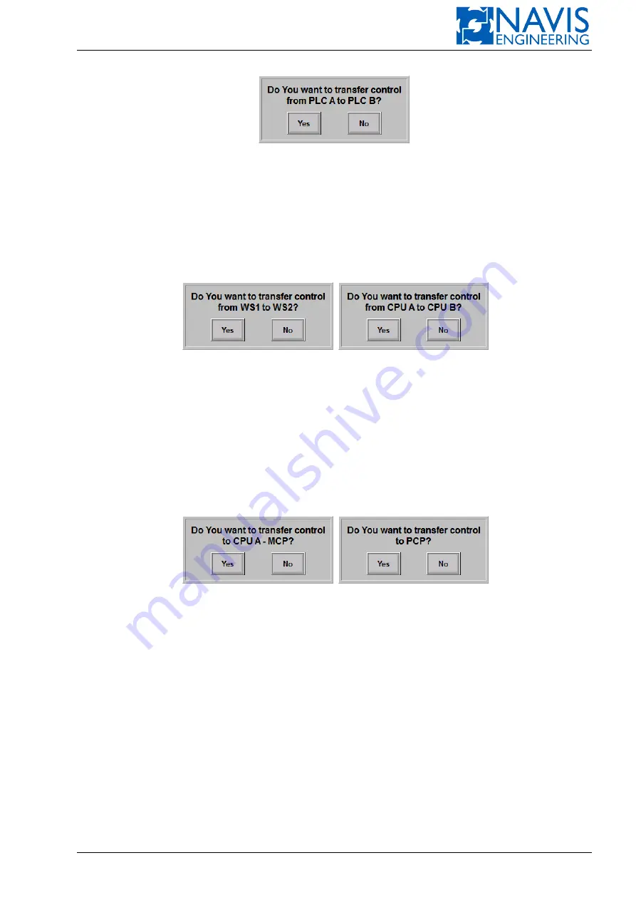
Figure 10.95: Example of the Dialog Box for Active PLC Change
2.
Change of Master Workstation/CPU
To change the master WS/CPU:
– press and hold for a few seconds dark-green softkey of the slave WS/CPU on the Mimic Diagram;
– press
OK
in the opened dialog box to apply the control transfer (see Figure 10.96).
(a) Master WS Change
(b) Master CPU Change
Figure 10.96: Example of the Dialog Box for Control Transfer to Another WS/CPU
3.
Control Transfer to MCP/PCP
To transfer control to another MCP (PCP):
– press and hold for a few seconds dark-green softkey of the slave MCP/PCP on the Mimic Diagram;
– press
OK
in the opened dialog box to apply the control transfer (see Figure 10.96).
(a) Control Transfer to MCP
(b) Control Transfer to PCP
Figure 10.97: Example of the Dialog Box for Control Transfer to Another Control Panel
10.12.2
Component State Tables
1.
Thruster and Power system component states table
.
The following data are displayed for each thruster:
– “Run”, “Rdy”, “Flt” indicators;
– circuit breaker (CB) state: On/Off;
– “Mode” text indicator (option) (see Section 6.1.3, page 105 for details).
The following data are displayed for each Power system component: “Run” indicator and CB state: On/Off.
TB state (On/Off) is displayed for each tie breaker.
2.
System state table
. States of the following components are displayed:
Doc. 000.JDP-10000-OME, rev.3.3.13/“2102.$–17A-Advanced”
236


