background image

Navini Networks, Inc.  


     Ripwave MX Modem User Guide 

Navini Networks, Inc.  


     Ripwave MX Modem User Guide 

10 

060210_pv1.6_Ripwave-MX Modem User Guide_40-00382-00b(4.4.2) 

hysical 

Characteristics


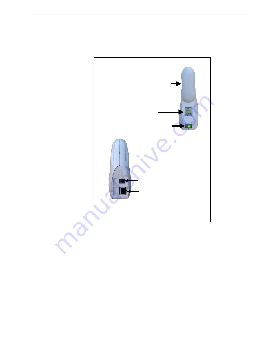
The following figure shows the physical characteristics of the 
Modem. 
 

LMX Modems (2.3, 2.4, 2.5-2.6, 3.4, & 3.5 GHz) 


P

Front 

Antenna

Liquid Crystal Display

On/Off Button

Back

Power Adapter Connection

Ethernet Cable Connection

Front 

Antenna

Liquid Crystal Display

On/Off Button

Front 

Antenna

Liquid Crystal Display

On/Off Button

Back

Power Adapter Connection

Ethernet Cable Connection

Back

Power Adapter Connection

Ethernet Cable Connection

10 

060210_pv1.6_Ripwave-MX Modem User Guide_40-00382-00b(4.4.2) 

Summary of Contents for Ripwave

Page 1: ...MX Modem models Part Number 40 00382 00 Revision B Version 1 0 PV1 6 February 10 2006 Proprietary All information disclosed by this document is the proprietary property of Navini Networks Inc and is...

Page 2: ...NI DIAGNOSTICS NAVDIAG 18 DEFINING THE ICONS 19 SIGNAL STRENGTH AND SIGNAL QUALITY BARS 19 HOW TO INCREASE THE STRENGTH AND QUALITY OF THE SIGNAL 20 HISTORY GRAPHS 20 PARAMETERS 21 SCREEN OPTION BUTTO...

Page 3: ...MX Modem User Guide CARE AND MAINTENANCE 30 31 ADDENDUM 1 RIPWAVE MX MODEM PC TROUBLESHOOTING 33 UPGRADING THE MODEM ADDENDUM 2 END USER SOFTWARE LICENSE AGREEMENT 38 3 060210_pv1 6_Ripwave MX Modem U...

Page 4: ...avini Networks Inc Navini Networks is a registered trademark The Navini Networks logo Zero Install Ripwave and Unwired by Navini are trademarks of Navini Networks Inc Other product and company names m...

Page 5: ...ck or serious damage to the equipment Do not allow any type of liquid to come in contact with the equipment Unplug the equipment from the power source before cleaning Use a damp cloth for cleaning Do...

Page 6: ...he battery with conducting materials 8 10 Do not equipment 11 Do not disassemble the equipment Removing covers exposes dangerous voltages or other risks a also voids the warranty Incorrect reassembly...

Page 7: ...ry Information FCC Notice CAUTION This device is a Radio Frequency transmitter It is exposure requirements for transmitting devices For all with window mount a minimum separation distance of 8 inches...

Page 8: ...location or even city to city as long as there is coverage in the area This manual will guide you through the simple process of installing the Modem and its monitoring software Please verify the conte...

Page 9: ...n Windows 982 Windo 2 2 Ensure that the pc network port is enabled CPU Pentium level or higher RAM 32 MB or the Operating System minimum whichever is greater Hard Drive 50 MB free disk space for the N...

Page 10: ...of the Modem LMX Modems 2 3 2 4 2 5 2 6 3 4 3 5 GHz P Front Antenna Liquid Crystal Display On Off Button Back Power Adapter Connection Ethernet Cable Connection Front Antenna Liquid Crystal Display O...

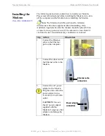
Page 11: ...talling the odem Th dem shou be positioned to minim ze itting Also e Modem should be pl ents sta ed 30 cm r more from a erson or us If the antenna is clos r than m from the us ustralian s Step Action...

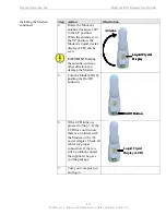
Page 12: ...n can damage the Modem to the UP position 5 Turn the Modem ON by pushing the On Off button in 6 If the LCD turns on proceed to Step 7 If the LCD does not turn on there is a problem with the Modem or t...

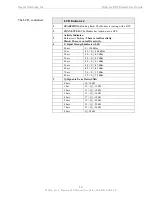
Page 13: ...ons po Below is a picture of the Modem s LCD and the various indications you will see on the LCD The following table defines the indicators that appear on the LCD T D Now that your Modem is installed...

Page 14: ...here is no traffi 4 ator SSI S Signal Strength Indic S 100 dBm 0 bars 1 bar 99 S 100 dBm S 99 dBm 2 bars 96 S 95 dBm 3 bars 92 91 dBm 4 bars 88 S S 87 dBm 5 bars 84 6 bars 80 S 83 dBm 6 S 79 dBm 7 bar...

Page 15: ...nder the Users tab Note The screenshots shown in these instructions were take from a laptop with Windows 2000 If yo o screens shown in the instructions Step Action Illustration 1 Before installing the...

Page 16: ...ere w p that InstallAnywhere has in indow appears The rogress bar indicates itialized 6 T vini Diagno Language screen appears Select a language and click to continue Windows 2000 Screen he Na stics OK...

Page 17: ...ppears Windows 2000 Scree Enter the name of the here you wish to ftware n folder w install the software Click Next to continue Note The default installation folder provided by the so is shown in the i...

Page 18: ...lose the window Windows 2000 Screen At the Insta ope nostics software application d uble click the n your desk To on n the Navini Diag Navini Diagnostics icon o o top Navini Diagnostics lnk The Connec...

Page 19: ...between the PC and the Modem or between the Modem and the Base Station is interrupted Signal Strength and Signal Quality are dynamic bar areas that indicate how well your Modem is receiving signals f...

Page 20: ...goes the better the SNR of the signal The color of the bars also gives an indication of the quality of the signal Green lines indicate an excellent signal or an SNR greater than 21 Orange lines indica...

Page 21: ...esis following the release number indicate the type of software load JD indicates Joint Detection while EN indicates Enhanced Nulling Analysis tatistics and About Each of these screens provides unique...

Page 22: ...sis screen press the Trend Analysis button inutes and updates once every second The graphic scrolls from right to left The Configurati ontinued c T S At the bottom of the screen is an Allow Customer S...

Page 23: ...ves you two options The first option n NavDiag provides help text on the functionality of the avDiag program The second option About NavDiag is quivalent to clicking on the About icon Screen T The Hel...

Page 24: ...stem software follow the procedure below Note The screen shots shown in these instructions were taken from a laptop with Windows 2000 If you have a Windows 98 XP or ME operating system the screens you...

Page 25: ...e battery packs are the Standard External Battery Pack S th att Hours of power T EBP and the Heavy Duty External Battery Pack HD EBP Bo batteries can be used with any of the LMX Modems The S EBP provi...

Page 26: ...tates associated with it The states are described below Battery LED Battery Charger Connected Modem Connected Switched On Modem On Off Button is Lit Comments Green Yes Not applicable Not applicabl e B...

Page 27: ...Do not attempt to plug the 12V adapter into the Modem s this can harm the Modem Chargin S Note1 As with any battery when the S EBP is left unused a long period of time it tends to lose its charge Whe...

Page 28: ...ds the center of the battery 2 Place the back slot of the Modem over the back prong of the battery 3 Place the front part of the opening on the Modem over the front prong on the battery 4 Release the...

Page 29: ...tor light that resides on the back end of the unit near the pig tail cord This light has four states associated with it The states are described in the following table Battery LED Battery Charger Conn...

Page 30: ...ouble free service o ensure on read instructio Keep the Modem free of d isture If th ets wet l to dry it i Handle the Modem gently Dropping it or mishandling it can cause damage to the plastic shell o...

Page 31: ...ns yo upgrade the Modem hod or systems that have ft release p Your Service Provider m so method is used for systems that have a softw or greater The latter two methods are used only if the Mod s not r...

Page 32: ...not have an IP address contact your Service Provider If you attempt to upgrade your Modem software through the Navini Diagnostics Tool and the computer does not have an assigned IP address you may se...

Page 33: ...in C configuration is transparent to the PC sers and is analogous to a m PC mal Ethernet LAN Check with your Service rovider if multiple IP addressing is required for your pa e Ethernet Modem is that...

Page 34: ...r the Navini L ito r the Navini Diagnostics router C R D E heck th uring results o installat It is locat e Navini process Th d under c P gnostics log file rogram F tallation by th D In DT 2 DT 2004 In...

Page 35: ...s NavDiag Status SUCCESSFUL stall Directory C Program Files NavDiag Uninstall Status SUCCESSF stall Uninstaller Navini Diagn nents Status SUCCESSF L stall Directory C Program F Status SUCCESSF C Progr...

Page 36: ...C Program File Status SUCCESSF stall File C Program File Status SUCCESSF stall File C Program Files NavDiag data images uninstall gif Status SUCCESSF stall Directory C Program F Status SUCCESSF L HKE...

Page 37: ...CCESSFUL Install File C Program Files NavDiag config NavDiag lcf Status SUCCESSFUL Install Directory C Documents and Settings luis Start Menu Programs NavDiag Status SUCCESSFUL Create Shortcut C Docum...

Page 38: ...acquires only the right to use the Software and related Documentation subject to the terms and conditions of this Agreement Buyer promises to keep the Software in confidence for the benefit of Navini...

Page 39: ...227 7013 Oct 1988 as applicable ARTICLE 3 TRADE SECRETS 3 1 Trade Secret Navini Networks Inc considers the Agreement to be a trade secret Navini Networks I licensed Software covered by this License c...

Page 40: ...SPECIFIC ITEM O AR 5 1 Consequential Damages TO THE MAXIMUM EXTENT PERMITTED BY THE APPLICABLE ERY OR LICENSING OF THE L CONSEQUENTIAL OR PUNITIVE DAMAGES D REGARDLESS OF THEORY OF LIABILITY EVEN IF...

Page 41: ...sponsible for any ay incur if Buyer appoints a vini s prior written consent Buyer shall c its directors officers employees agents ect and by Navini Networks Inc However if the subcontractor is pre dam...

Reviews: