background image


www.NavePoint.com 

[email protected] 


2.


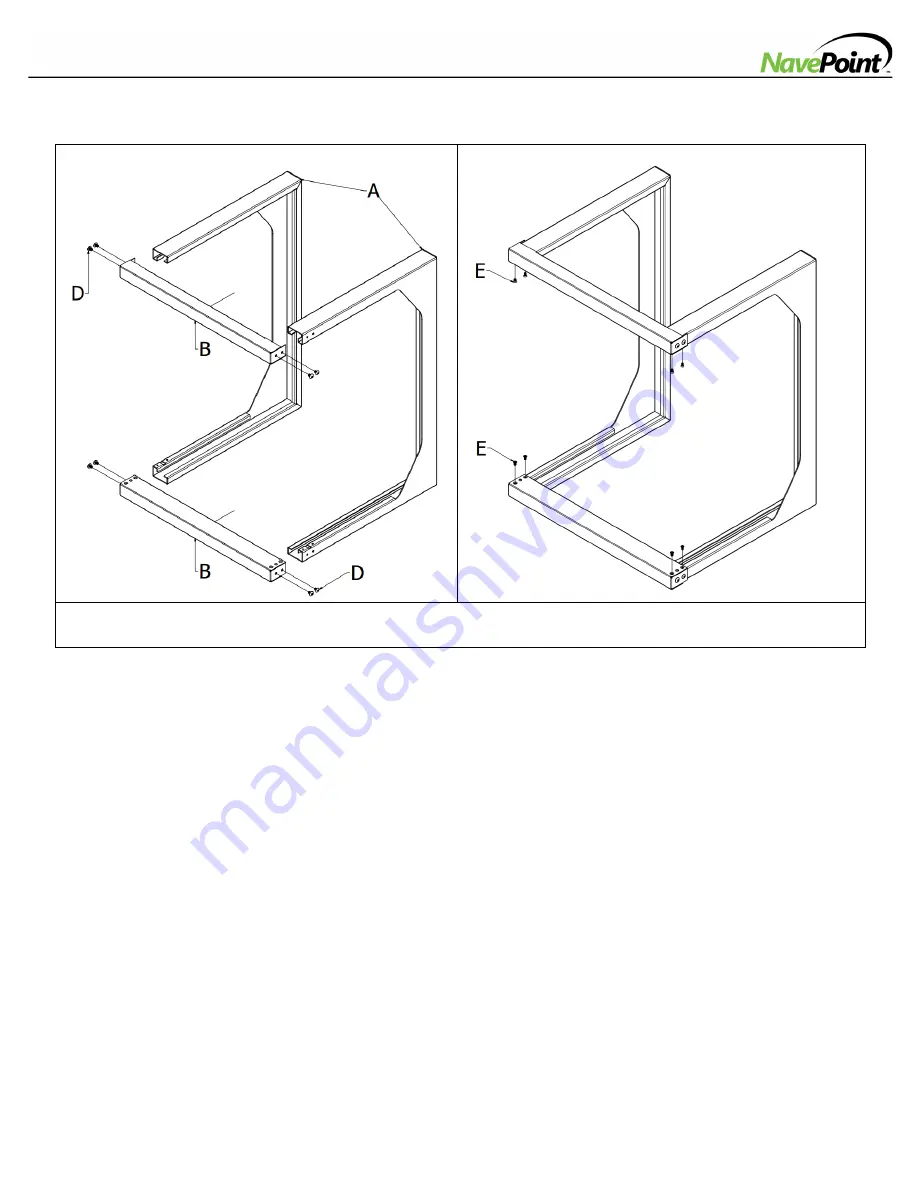
Rack Assembly 

STEP 1 


STEP 2 


STEP 1.

  Attach the 2 Horizontal Support Bars (B) to the Wall Mounting Frames (A) using 8 M5 Screws (D). 

STEP 2.  

Secure them with 8 M4 Screws (E). 


Summary of Contents for Swing Gate Wallmount Rack

Page 1: ...y a qualified installer NavePoint cannot be held responsible for damage to equipment or personal injury resulting from improper use or installation of product Maintenance Check that the product is secure and safe to use at regular intervals at least every three months Limitations of Liability In no event will NavePoint LLC be liable for any damages whether direct or indirect special punitive incid...

Page 2: ...m 1 Parts Identification A Wall Mounting Frame x2 B Horizontal Support Bar x2 C Equipment Mounting Frame x1 D E F G H M5 Screws x8 M4 Screws x8 Metal Sleeves x2 Plastic Sleeves x2 M6 Mounting Screws x10 I J M6 Cage Nuts x10 12 24 Mounting Screws x10 ...

Page 3: ...vePoint com 3 customerservice navepoint com 2 Rack Assembly STEP 1 STEP 2 STEP 1 Attach the 2 Horizontal Support Bars B to the Wall Mounting Frames A using 8 M5 Screws D STEP 2 Secure them with 8 M4 Screws E ...

Page 4: ...ert 2 Plastic Sleeves G into the holes on the upper Horizontal Support Bar B STEP 4 Secure the Equipment Mounting Frame C to the built frame make sure the latch pins click into both the Metal Sleeves F and the Plastic Sleeves G Note The Equipment Mounting Frame C can be installed with either the tapped screw holes or the squared holes facing forward for equipment mounting purposes ...

Page 5: ...are spaced 17 75 451mm as reflected in the diagram Warning Do not attempt to mount to wall when equipment is already mounted inside the rack The rack can hold up to 100 pounds evenly distributed 50 pounds when Equipment Mounting Frame is in open position Make sure the wall surface can hold both the weight of the cabinet and the rack mounted equipment 4 Equipment Installation 1 Rack Unit ...

Page 6: ... the inside of the Equipment Mounting Frame C insert one of the flanges of the cage nut through the square opening Press it against the side of the square opening b Compress the cage nut at the sides slightly to allow the remaining flange to fit through the square opening When the cage nut is properly installed both flanges will protrude through the square opening and will be visible on the outer ...

Page 7: ...www NavePoint com 7 customerservice navepoint com Tapped Hole Mounting Use the included 12 24 Mounting Screws J to secure your equipment to the Equipment Mounting Frame C ...

Reviews: