background image

9250 X

YLON

A

VENUE

• M

INNEAPOLIS

, MN 55445  •  U.S.A.

800-245-0267 • 763-315-5300 • F

AX

763-535-8255 • F

AX

800-648-7124

W

EB

S

ITE

: www.nationalequipment.com • E-M

AIL

[email protected]

National

Flooring Equipment, Inc.
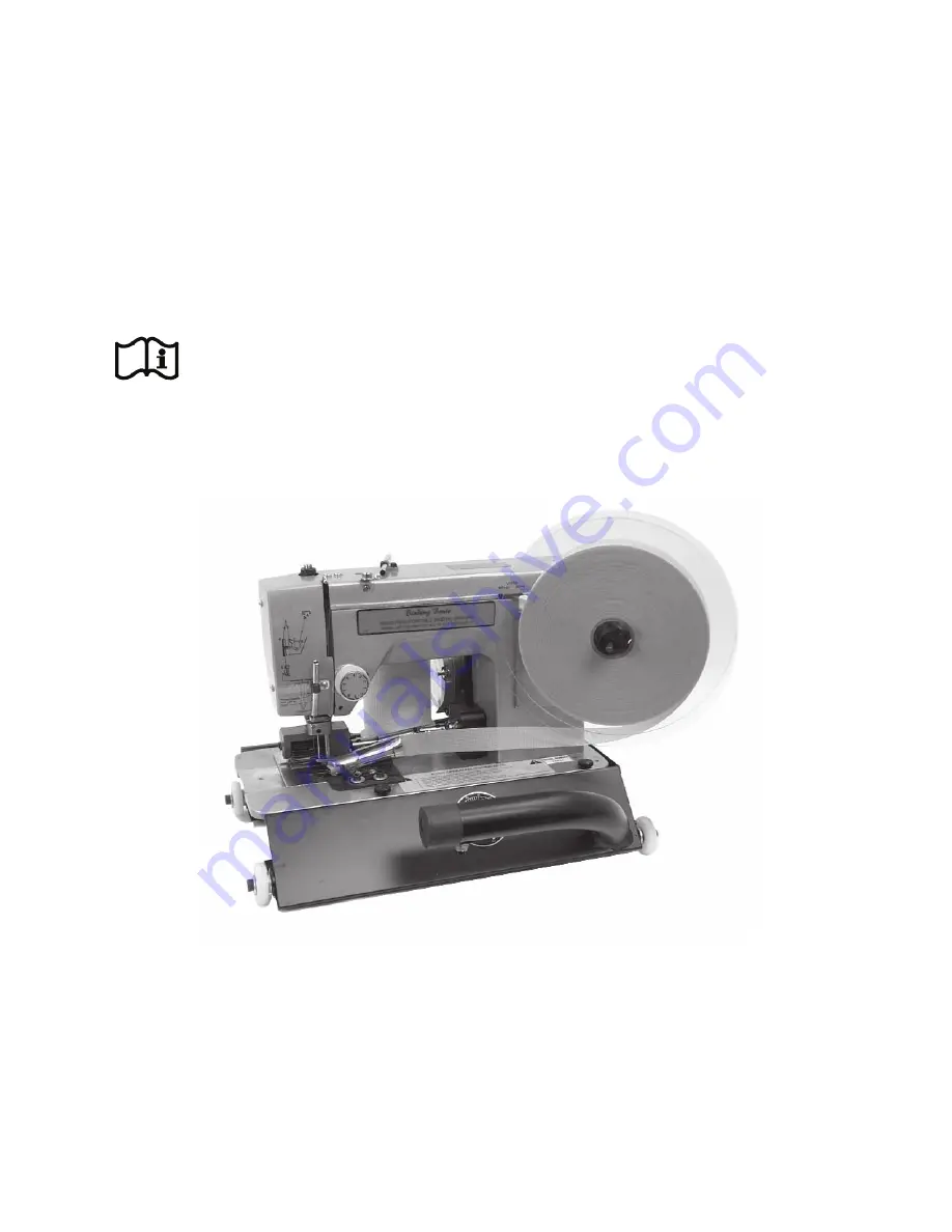
#155 DOUBLE PULL

BINDING BRUTE

INSTRUCTION MANUAL

Read Manual Before Operating Machine

Summary of Contents for 155

Page 1: ...00 245 0267 763 315 5300 FAX 763 535 8255 FAX 800 648 7124 WEB SITE www nationalequipment com E MAIL info nationalequipment com National Flooring Equipment Inc 155 DOUBLE PULL BINDING BRUTE INSTRUCTIO...

Page 2: ...6 A Lubrication 16 B Shuttle Area 16 C Entire Machine 16 D Operation Tips 16 Adjustments 17 20 A Check Needle Height 17 B Adjust Needle 18 C Needle To Hook Clearance 19 D Race Cover Spring Clearance 2...

Page 3: ...tacting the tool or extension cord Operator should be aware of who is around them and their proximity 8 PROTECT OTHERS IN THE WORK AREA Provide barriers or shields as needed to protect others from deb...

Page 4: ...the influence of drugs alcohol or any medication causing decreased control 18 STARTING MACHINE On off switch must be in off position before connecting to power source 19 UNPLUG EQUIPMENT When it is n...

Page 5: ...ted to the tool s grounding system and must never be attached to an electrically live terminal Your tool must be plugged into an appropriate outlet properly installed and grounded in accordance with a...

Page 6: ...you are using an extension cord outdoors make sure it is marked with the suffix W A W in Canada to indicate that it is acceptable for outdoor use Be sure your extension cord is properly wired and in g...

Page 7: ...2 Instruction DVD Instruction Manual Lubricant Binding Reel Centering Plug Accessory Kit containing Prewound Bobbins 8 5 32 Allen Wrench Needles 1 Ten Pack 3 32 Allen Wrench Tweezers Binding Tape 1 Ro...

Page 8: ...uide B Enter Tension Discs C Exit Tension Discs D Take up Spring E Take up Lever F Lower Thread Guides G Needle Block H Needle See Figure 2 NOTE Assure thread is bottomed in the tension disc B C This...

Page 9: ...l thread through slot in the bobbin case See Figure 3 c Continue by pulling thread under tension spring and up through slot in spring See Figure 4 Refer to Step 7c to check for proper thread feed tens...

Page 10: ...tening set screw DO NOT OVER TIGHTEN Page 10 THREADING INSTRUCTIONS CAUTION Replacement needles MUST be of the correct type and installed correctly for proper machine operation Proper needle type for...

Page 11: ...appropriate at this point to note that whenever you re thread the machine to make sure the thread is properly seated between the tension discs Lack of upper tension can result in looping of upper thr...

Page 12: ...in the folder slot push the tape until you can grasp tape end at folder exit Pull several inches of tape through folder and out under the needle as it would appear while stitching Tape as being fed fr...

Page 13: ...ly with your right hand until needle enters needle plate and returns to highest point Avoid making these changes with the needle below the needle plate or in carpeting IMPORTANT Certain carpet types w...

Page 14: ...t type you intend to bind Other folder types available are as follows Page 14 FOLDERS Approximately 1 8 from edge of tape Right stitch off edge of tape ZIG ZAG STRAIGHT 3 4 7 8 1 2 2 3 etc 1 1 4 Clean...

Page 15: ...g the folder by allowing approximately 1 8 space between them 3 When correctly adjusted the folder positions can be marked on a piece of masking tape applied at the front edge of the folder 4 Use of t...

Page 16: ...associated with the stitch selector Repeat this procedure in the needle bar area behind the front cover and the lower area after removing the pan NEVER lubricate the tension control This is also a goo...

Page 17: ...u turn the handwheel counterclockwise the hook will travel clockwise reverse rotation and travel counterclockwise to a position where the point of the hook is approximately 1 8 behind the needle and r...

Page 18: ...part 126 164 See Figure 1 2 Slide needle bar part 126 172 slightly up or down 3 Tighten set screw in drive collar 4 Recheck adjustment using procedure on Page 17 Access Hole Interior View Access Hole...

Page 19: ...is visible Turn handwheel counter clockwise until the point of the hook passes behind the needle Stop when the point is approximately 1 8 past the needle See Figure 1 The hook should just touch but no...

Page 20: ...Install hook Recheck needle to hook clearance IMPORTANT When adjustments are completed install the needle properly Scarf flat side on right hand side Symptoms of a problem with this adjustment are de...

Page 21: ...or broken Replace drive spring in Shuttle and or in Binding on carpet with plastic backing i e Unibond Use lubricant Cut on Carpet Bottom Burrs on shuttle hook Deburr hook Binding carpet with backing...

Page 22: ...corner 16 Slowing the machine down with the speed control included with Model 155 or optional 126 N with Model 126 will also aid in making corners circles and curves If no speed control is used trigge...

Page 23: ...s at a slight angle away from the edge at the front Trial and error maybe necessary with slightly more movement to the left See Figure 1 2 Loosen the folder to bracket screws By trial and error moveme...

Page 24: ...ITCHING INSTRUCTIONS NORMAL OUTSIDE CORNER Sew over end then trim flush with edge Leave approximately 2 3 strip each time Sew over trimmed end Repeat on each corner 1 2 3 When completed fold and glue...

Page 25: ...ving a 2 to 3 strip Leave a 2 to 3 strip at the end Raise needle and cut Fold strip under 1 2 3 Place folded strip in folder Sew down that side Repeat 1 thru 3 on each corner 4 When completed fold and...

Page 26: ...hose done by folding over and gluing You have to raise the feed roller watch the needle and move the carpet only when the needle is up Zig zag should be used on corners Straight stitching is not recom...

Page 27: ...STITCHING INSTRUCTIONS INSIDE CORNERS continuedI Push fibers into cut Flatten tape from both sides and glue over cut 3 Top of completed corner 4 Fold back sewed side Start at cut 2 Fold back at cut an...

Page 28: ...RUCTIONS B SECOND WAY Handsew the corners Sew as close to corner as machine will allow and stop Slide carpet in from back of machine and continue sewing Allow enough binding to reach corner Hand stitc...

Page 29: ...SCREW 126 21 FRONT COVER LATCH 126 23 FRONT COVER HINGE 126 24 2 UPPER THREAD TENSION CONTROL SEE PG 36 126 52 MOTOR POWER RECEPTICLE 126 53 POWER CORD STRAIN RELIEF RETAINER 126 54 POWER CORD STRAIN...

Page 30: ...NEEDLE BAR CARRIER 126 158 NEEDLE BAR SPRING 126 160 NEEDLE BAR DRIVE LINKAGE ASSEMBLY 126 161 NEEDLE BAR DRIVE LINK W RETAINER 126 162 NEEDLE BAR DRIVE LINK 126 163 NEEDLE BAR SET SCREW NOT SHOWN 12...

Page 31: ...OCK SCREW ONLY NOT SHOWN 126 557 ZIG ZAG DRIVE GEAR SET SCREW ONLY 2 NOT SHOWN 126 574 ZIG ZAG DRIVE WORM GEAR 126 600 LATCH PIN FOR COVER 126 1171 RACE COVER RETAINERS 2 126 1172 SHUTTLE BODY BUSHING...

Page 32: ...CREW NOT SHOWN 73346 5 16 X 1 2 SHOULDER BOLT 73353 5 16 X 5 8 SHOULDER BOLT 74406 10 32 X 3 8 PHILLIPS PAN HEAD MACHINE SCREW 2 74408 10 32 X 1 8 CUP POINT SOCKET SET SCREW 3 74409 10 32 X 3 16 CUP P...

Page 33: ...E DISKS BOBBIN CASE This machine uses bobbin case with an eyelet Part 126 112 1 Thread must pass through eyelet in bobbin case for proper operation Tension on the bobbin thread should be light You hav...

Page 34: ...26 600 Latch Pin For Cover 126 C4T Thread Stand Bolt Nut 126 CS Tape Centering Plug for 7 8 Tape 126 Disc Binding Disc Set Includes Disc 1 Disc 2 Disc Collar Thumb Screw 126 Disc1 Rear Disc 126 Disc2...

Page 35: ...Pan Thumb Screw 3 155 528 Switch Washer 155 530 Speed Control Back Plate 155 533 Speed Control Knob PART DESCRIPTION 155 537 Pan Wheel w Bearing 4 155 5260 220 V Pan Assembly 155 5290 220 V Switch As...

Page 36: ...ve Motor Upper Mount Screw 2 126 198 Drive Motor Mounting Plate 126 199 Drive Motor Belt 126 1910A Drive Motor 110V Brushes 2 PART DESCRIPTION 126 1910B Drive Motor 230V Brushes Not Shown 73002 1 4 Sp...

Page 37: ...Roller Dowel Pin x 2 2 155 573 Needle Plate Rear Screw 2 155 575 Needle Plate Retainer Bar PART DESCRIPTION 155 577 Shuttle Recess Plate 155 577 1 Needle Plate Retainer 155 577 2 Shuttle Access Plate...

Page 38: ...126 544 Stitch Control Assembly 126 544A Repl Stitch Control Knob Only PART DESCRIPTION 126 545 Stitch Control Assembly Mounting Screw 3 126 546 Shuttle Oscillator Control Link w Screw 126 549 Stitch...

Page 39: ...125 Connecting Rod Lower Spindle 126 126 Connecting Rod Lower Spindle Nut 126 127 Shuttle Oscillator Crank Screw Only 2 Not Shown 126 128 Shuttle Oscillator Crank w Screws PART DESCRIPTION 126 130 Shu...

Page 40: ...Collar w Set Screw 126 165 Needle Bar Drive Linkage Assembly Pin w E Clip Set Screw 126 166 Needle Bar Drive Linkage Assembly Pin E Clip Not Shown 126 172 Needle Bar Presser Foot Assembly w Set Screw...

Page 41: ...126 A2 Style A Size D 72 yards Nylon comes with Binding Brute Heavy Duty 126 A3 Style F 80 yards Cardboard sides for use with binders other than National s THREAD 126 E Clear 4 300 yards per spool Si...

Page 42: ...her brand machines Custom folders available inquire 126 G 126 CF 126 CF 7 8 raw edge 126 D 1 1 4 raw edge 126 D1 1 1 4 clean top Tucks top edge under 126 D2 1 1 4 clean top and bottom Tucks top and bo...

Page 43: ...f purchase receipt C O D freight return shipments will not be accepted All returns must have a return authorization number Contact National to obtain one All guarantee findings will be up to the consi...

Page 44: ...roblems Encountered Check One Repair Do you wish to be contacted before repairing Yes No Return Contact National if a loaner is needed Return Authorization Number Date Customer Number Purchased From r...

Reviews: