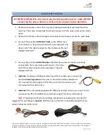
background image

BHM 

09/02/15 

NTV-DOC242 


Agreement

End user agrees to use this product in compliance with all State and Federal laws. NAV-TV Corp. would not be held liable for 

misuse of its product.  If you do not agree, please discontinue use immediately and return product to place of purchase. This product is 

intended for off-road use and passenger entertainment only.  

4 | 

P a g e


CAN Gateway 

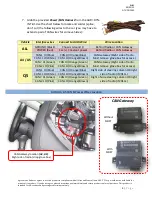
7.


Grab the provided 

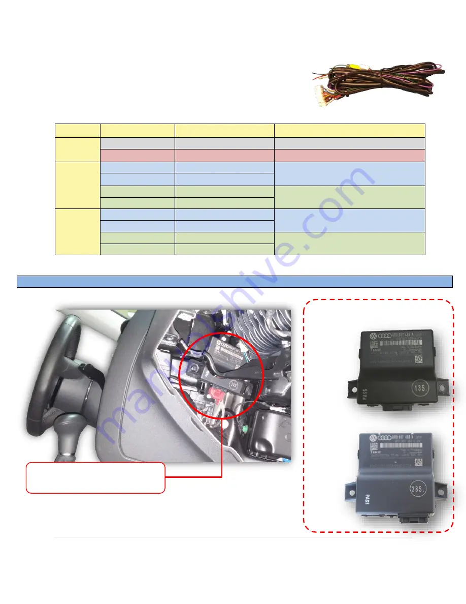
Power/CAN Harness

 from the AUDI-DYN-

INT kit. Use the chart below to locate and solder (splice, 
don’t cut) the following wires to the car (you may have to 
extend a pair of CAN wires for some vehicles): 


AUDI A4, A5 CAN & Power Wires Location 


Vehicle 

Interface wires 

Connect to AUDI Wire: 

Wire Location 


ALL


GROUND (Black) 

Chassis Ground (-) 

Behind Radio or CAN Gateway 

POWER (Red) 

12v (+) Constant power 

Behind Radio or CAN Gateway 


A4 / A5


CAN 1 HI (Blue) 

CAN HI (Orange/Blue) 

CAN Gateway (Right side of radio. 

Must remove glove box for access.) 

CAN 1 LO (White)  CAN LO (Orange/Brown) 

CAN 2 HI (Green) 

CAN HI (Orange/Green) 

CAN Gateway (Right side of radio. 

Must remove glove box for access.) 

CAN 2 LO (Pink) 

CAN LO (Orange/Brown) 


Q5


CAN 1 HI (Blue) 

CAN HI (Orange/Blue) 

Right side of steering column OR right 

side of radio (if 2014+) 

CAN 1 LO (White)  CAN LO (Orange/Brown) 

CAN 2 HI (Green) 

CAN HI (Orange/Green) 

Right of side steering column OR right 

side of radio (if 2014+) 

CAN 2 LO (Pink) 

CAN LO (Orange/Brown) 

With 

MOST 

Without 

MOST 

CAN Gateway location 

(A4, A5)

Right side of radio (drop glove box) 
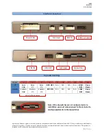
Summary of Contents for AUDI DYNAMIC-INT

Page 1: ...eo expansion board cable harness 3950 NW 120th Ave Coral Springs FL 33065 TEL 561 955 9770 FAX 561 955 9760 www nav tv com info nav tv com AUDI DYNAMIC INT NTV KIT700 Overview The AUDI DYN INT Kit int...

Page 2: ...passenger entertainment only 2 P a g e Upon button presses Interface Connectors Dip Switch Settings Dip SW 1 2 3 4 5 6 7 8 9 10 UP Skips RGB Skips V1 Skips V2 RVC OFF N C N C N C N C HIGH RES Keep Dow...

Page 3: ...nects to the interface at the port labeled LVDS OUT 4 Connect the provided LVDS IN Cable to OEM 10 pin square connector previously connected to the screen removed in step 1 The other end of this cable...

Page 4: ...res Location Vehicle Interface wires Connect to AUDI Wire Wire Location ALL GROUND Black Chassis Ground Behind Radio or CAN Gateway POWER Red 12v Constant power Behind Radio or CAN Gateway A4 A5 CAN 1...

Page 5: ...d red for power 10 Connect the signal for your camera to the yellow RCA among the Power CAN Harness labeled CAMERA 11 Connect the 24 pin white plug from the Power CAN Harness to the port on the AUDI 0...

Page 6: ...held liable for misuse of its product If you do not agree please discontinue use immediately and return product to place of purchase This product is intended for off road use and passenger entertainm...

Page 7: ...d out of reverse OEM similar If the user wants only an AUX video input not front camera leave this option OFF and use DIP SWITCH 2 for adding AUX Video input selectable via the provided push button sw...

Page 8: ...se will show the connected rear camera image with Dynamic Guidelines which correspond with the steering wheel geometry If a front camera was added and Automatic front camera switching was turned on wh...

Page 9: ...OUT are connected at the proper location at the screen B Verify the video cables are seated all the way C Verify the Dip Switches are set correctly Q Rear camera image does NOT appear A Make certain...

Reviews: