background image

© 2011 

Nautilus Hyosung Inc. 

All Rights Reserved

.


A-2 


Installation Manual 

Appendix 


Bottom Section 

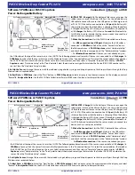
Remove the desiccant attached on the bottom. 


Removing the locking section from the main body of Cash & Check In Module


Escrow Section 

1. Move the location of the Red Screw ”A” fastened on the Escrow Section. 

(Unfasten the Screw ”B” and open the cover. After Moving the location of the 
Screw ”A”, fasten the screw “B” again) 

2. Move the location of the Screw “C” fastened on the Body Section. 


Moving the location of the screw fixing the guide on Escrow Section 


Transport Section of BM2 

Disassemble the green screw. 


Removing the screw fixing the transport section of BM2 


Summary of Contents for MONiMAX7600

Page 1: ...Installation Manual MONiMAX7600 System V01 00 02 2015 05 11 2011 Nautilus Hyosung Inc All Rights Reserved...

Page 2: ...ew Publication All 2 V01 00 01 2012 08 29 Added Height and Depth Main Fascia Items Chapter 3 3 V01 00 02 2015 05 11 Added the approximate weight of MX7600 Chapter 3 2011 Nautilus Hyosung All Rights Re...

Page 3: ...nd Space 3 1 Packing Dimensions 3 1 Weight Dimensions 3 2 Height and Depth Main Fascia Items 3 4 Fascia Item Locations for Voice Guidance 3 5 Recommended Installation and Service Clearance 3 6 Chapter...

Page 4: ...phone numbers provided to you separately What is in This Manual In addition to installation guidelines for the MX7600 this manual includes important warnings you must take into consideration during in...

Page 5: ...ance refer to the supervisor operator and technician s tasks performed to keep the ATM operational Screen refers to the text appearing on the customer display Abbreviations of ATM The abbreviations li...

Page 6: ...0 OPL Operation Panel for Customers to Operate 31 OSD board On Screen Display Board 32 P S Power Supply 33 PIN Personal Identification Number 34 PNC Panel Control Board 35 PRT Endorsement Module 36 PT...

Page 7: ...operate the equipment Note This equipment has been tested and found to comply with the limits for a Class A digital device pursuant to part 15 of the FCC Rules These limits are designed to provide re...

Page 8: ...ce the equipment in an area away from any combustible materials The equipment may catch on fire from overheating or short circuit of the power supply unit 5 Disassembly Warnings Do not disassemble or...

Page 9: ...cument Related documents are listed as follows If needed please contact the Nautilus Hyosung technical support team or maintenance team for copies Operator Manual Maintenance Manual To contact the Nau...

Page 10: ...1 Removes inconvenience which occurs when bank tellers directly handle cash and checks with customers and relieves workload upon tellers by processing deposit withdrawal of cash check automatically 2...

Page 11: ...g Inc All Rights Reserved 2 2 Installation Manual Chapter2 Introduction System Identification Label The System Label below shows the layout of the product identification label which is fixed inside th...

Page 12: ...intense direct light is reflected off the LCD screen 2 Avoid locations where strong static electricity can occur 3 The floor must allow easy wheelchair access from the front or the side 4 Space requir...

Page 13: ...Hyosung Inc All Rights Reserved 3 2 Installation Manual Chapter3 Installation Information Weight Dimensions Approximate Weight 820kg 1 807 79Ibs The figure below shows the dimensions of MX7600 ATM vie...

Page 14: ...2011 Nautilus Hyosung Inc All Rights Reserved 3 3 Installation Manual Chapter3 Installation Information The figure below shows the dimensions of the MX7600 ATM viewed from the side...

Page 15: ...nd allows good accessibility and convenience for both of unhandicapped and handicapped people The height and depth of main fascia items Symbol Height Depth Remarks A 1217mm 47 91inch Top of the touch...

Page 16: ...3 5 Installation Manual Chapter3 Installation Information Fascia Item Locations for Voice Guidance Unit MCU SPR CDU CCIM Symbol A B C D Distance From No 5Key 193 7mm 7 6 In 153 5mm 6 0 In 140 8mm 5 5...

Page 17: ...tion Recommended Installation and Service Clearance The following diagrams describe the recommended areas required for installing and servicing the MX7600 Plan View Note Hyosung highly recommends that...

Page 18: ...utilus Hyosung Inc All Rights Reserved 3 7 Installation Manual Chapter3 Installation Information Thefollowing diagram describes the recommended area required for installing and servicing the MX7600 Si...

Page 19: ...he nails from the palette Refer to figure below 3 Remove the lid then box from the top Do not discard the packaging materials until you have verified any shipping damage claim Contact your distributor...

Page 20: ...3 Lifting equipment using a lifting device 4 Moving this ATM machine to the installation site PRECAUTION MX7600 ATM machine is very heavy equipment and can cause injuries if not handled with caution R...

Page 21: ...o that the unit will not tip over when opening the upper lower modules or the door 2 Place the anchor bolt location sheet where the MX7600 is to be installed 3 Drill the correct diameter and depth hol...

Page 22: ...2011 Nautilus Hyosung Inc All Rights Reserved 4 4 Installation Manual Chapter4 System Installation Anchor bolts location sheet sample...

Page 23: ...nected to cash dispenser card reader receipt printer CCIM control electronics and so on It is likely that one of them became disconnected during transport and may cause unexpected problem after the in...

Page 24: ...tion 1 Move the location of the Red Screw A fastened on the Escrow Section Unfasten the Screw B and open the cover After Moving the location of the Screw A fasten the screw B again 2 Move the location...

Page 25: ...ever Tie from the main body Separating the Cassette Section Cash Check Cassette Section 1 Open the box and take out the cassette 2 Separate the key attached on the top of the cassette And insert the k...

Page 26: ...he Cassette And insert the key in the cassette key hole 3 Open the door with the key Then remove the tape on the bottom of the middle guide Installing Section Procedure to remove the protective materi...

Page 27: ...5 Installation Manual Appendix Installing the PRT Cartridge Section 1 Pulling the green knob until stopping at the same time rotating right and pulling it completely 2 After opening the green grip in...

Page 28: ...ndix 3 And then release the green grip the ink cartridge is locked Before mounting it see the ink cartridge installation guide on the packing bag 4 Push the green knob completely to the left arrow dir...

Page 29: ...2011 Nautilus Hyosung Inc All Rights Reserved Notes 1 Installation Manual Notes Notes...

Reviews: