Page 8
B. Critical Overview of Component Installation
1.
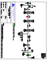
This is an important overview section, which will make it easier to identify each
RF component in the system, and also ensure that each component will be located
in its proper position and orientation. While going through this overview section,
refer to the RF schematic and Component Layout Drawing.
2.
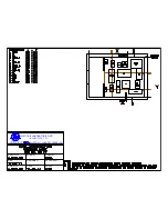
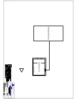
The Component Layout Drawing shows the correct placement of all the RF
components.
3.
The set of factory photos of the ATU network mockup provide numerous
examples of the components mounted on their respective component panels, as
well as the identifying labels that are used on all components and all relevant
drawings. An example photo noting typical ATU components is given below
(Note the photo is not for this particular system, but is a representative factory
photo).
Figure 1: Component Panel details
Each insulator and all
associated hardware must
be securely mounted to
the component panel
.
Capacitor mounted
on its component
panel
Coil mounted on its
component panel
Example of
component panel
Identifying label for the component. This
label (e.g., “L106” for this example) is used
to identify each component on the RF
schematic, on the component panel, and on
the layout drawing.
Summary of Contents for NX100
Page 2: ......
Page 15: ...Page 13...
Page 16: ...Page 14...
Page 17: ......
Page 20: ......
Page 21: ......
Page 23: ......


