Stage 3 of Tuning Procedure
Final Setting of L and R Tuning Taps (
LOCAL
control,
TUNE SETUP
off)
Page 2-16
ATU-HP Technical Instruction Manual
Issue 2.0
Section 2 Preparation for Use and Installation
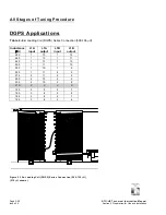
Table 2-3:
T1 Matching Transformer 50 Ohm Connections
Antenna System Resistance (
Ω
)
T1
Connections
2 3 4 5.6 7 8 9 12.5 16 18 20 22 25 28 32 35 37 39
In
(Blue
wire) 3 6 5 4 6 3 5 6 5 3 6 4 5 6 3 4 5 6
Out
(Red
wire) 7 8 8 8 9 8 9 2 2 9 3 2 3 4 2 3 4 5
Paragraph 2.5 continued
(l) Press the ATU control/monitor PWB’s
TUNE SETUP
switch so that its
associated LED and the
R TUNING –
INHIBIT
LED turn off.
WARNING
Ensure the transmitter is off when
making adjustments on the ATU-HP.
Lethal voltages are present when any
level of RF is applied to the ATU-HP.
(m) Turn off the transmitter. Configure the
RF wiring between the ATU control/
monitor PWB’s terminal block
(A1TB1) and the matching
transformer terminal blocks (TB1 and
TB2) as shown in Figure 2-9.
Reconnect blue wire to capacitor bank.
(n) Using Table 2-4, select the nearest
operating frequency and determine
the ‘R match’ value.
Figure 2-9 - Post-Resistive Tuning RF Wiring Connections
A1TB1
T1
The termination points for
the T1 INPUT (green) and
T1 OUTPUT (red) wires,
determined in steps (n)
through (u), can be on either
of T1’s terminal blocks.


