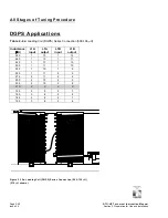
Stage 1 of Tuning Procedure
Initial Setting of L Tuning Taps (
LOCAL
control,
TUNE SETUP
on)
ATU-HP Technical Instruction Manual
Page 2-13
Section 2 Preparation for Use and Installation
Issue 2.0
Paragraph 2.5 continued
(g) With the ATU-HP connected to both
the transmitter and the antenna
system, turn on the transmitter (use
CW mode for NDB transmitters) and
set its output power for 100 W
(maximum).
(h) Using the flow diagram illustrated in
Figure 2-6, tune the ATU-HP loading
coils. Disregard the status of the
R
TUNING
LEDs on the ATU control/
monitor PWB during this procedure.
Figure 2-6 - Flow Diagram – Loading Coil Tuning
Turn transmitter
off. Increase
inductance to next
higher setting as
per appropriate
Table
2-6
(a–f).
LOADING COILS
TUNED
Turn transmitter
off. Decrease
inductance to next
lower setting as
per appropriate
Table
2-6
(a-f).
Turn transmitter on
Wait for
L TUNING
-
NORMAL
,
MAX
LIMIT
or
MIN LIMIT
LED
to turn on.
Check
L TUNING
LEDs on PWB
Which
L
TUNING
LED is
on?
TUNE LOADING
COILS
L TUNING R TUNING
MAX LIMIT
INCREASE
NORMAL
DECREASE
MIN LIMIT
INHIBIT
L TUNING R TUNING
MAX LIMIT
INCREASE
NORMAL
DECREASE
MIN LIMIT
INHIBIT
L TUNING R TUNING
MAX LIMIT
INCREASE
NORMAL
DECREASE
MIN LIMIT
INHIBIT


