Ni-Cd and Ni-MH Configuration Options
It is possible to charge Ni-Cd and Ni-MH cells either with
Fast PWM or Slow PWM modes. The Fast PWM mode
provides a higher quality charge than the Slow PWM mode.
Cost-sensitive applications can implement the Slow PWM
mode, which reduces the number of required components.
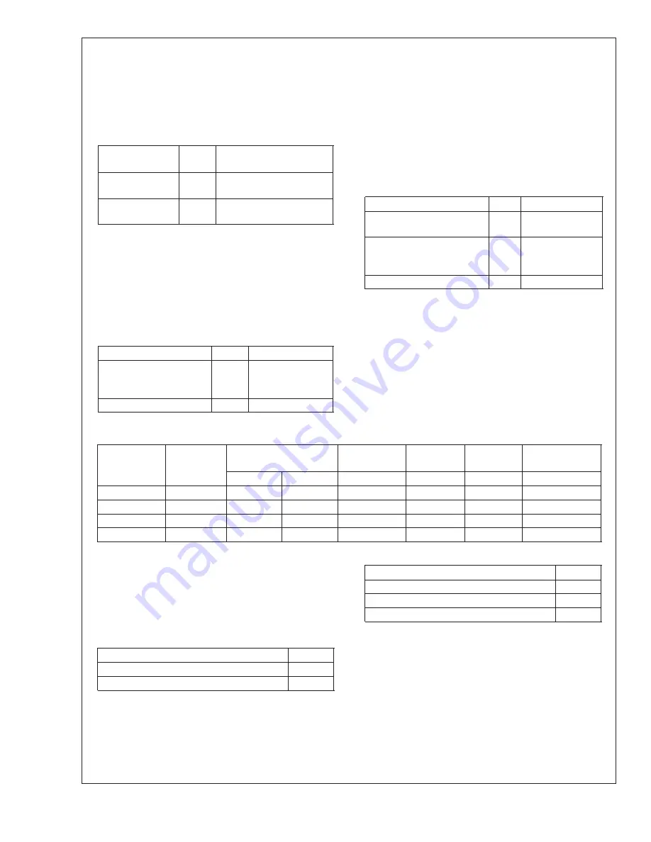
TABLE 3. Ni-Cd/Ni-MH Charge Regulation
Charge
Regulation
J7
Note
Fast PWM Mode
V
CC
Note: Set Feedback
Current Range
Slow PWM
GND
Note: J10 Must Not Be
Open
Note: During the charge cycle of Ni-based batteries, should J6 (SEL3) come
loose, the LM3647 charge control will switch from Fast PWM Mode to
the Slow PWM (ON/OFF) Mode. Since the regulation signal is in-
verted, the battery will be exposed to maximum voltage and current.
When using the LM3647 to charge both Ni-based and Li-Ion batteries,
hardwire SEL3 directly to V
CC
. (The voltage feedback resistor values,
normally selected via J11 & J12, will need to be modified slightly when
charging 4.1V/cell Li-Ion battery-packs.) For production-intent Ni-Cd/
Ni-MH and Li-Ion designs, Pin 1 should be connected directly to V
CC
to
prevent potential overstress to the battery pack.
TABLE 4. Ni-Cd/Ni-MH Charge Control
Current Control
J6
Note
LM3647 Current
Feedback
V
CC
Note: Set
Feedback Current
Range
External Current Control
GND
In order to ensure a fully charged battery, a Maintenance
Charge is applied to counter the effects of self-discharge.
Another method to ensure a fully charged battery is to mini-
mize the effects of memory. Ni-Cd cells are prone, and to a
lesser extent Ni-MH cells, to a voltage depression effect
known as
″
memory
″
. This effect occurs when cells are rou-
tinely partially discharged. To minimize this effect, the
LM3647 can discharge Nickel-based cells before starting the
normal charge sequence. Enabling this feature requires that
a suitable discharge resistor is installed at J15. A typical
discharge rate for this purpose is 0.2C.
TABLE 5. Ni-Cd/Ni-MH Discharge Setting
Discharge Maintenance
J2
Note
No Discharge before
Charge
V
CC
Discharge before Charge
N.C.
Note: Install
Discharge
Resistor
Maintenance Charge Only
GND
Lithium-Ion Configuration
Li-Ion cells have a nominal voltage of either 3.6V or 3.7V and
during charging can reach a peak of 4.1V or 4.2V, respec-
tively. Cells are first charged with a constant-current until it
reaches its maximum voltage and then charged with a
constant-voltage until current drops to a preset threshold.
Charging Li-Ion cells requires finer charge control than
Ni-cells, which omits the possibility of using Slow PWM
mode; settings for Fast PWM will need to be used.
TABLE 6. Li-Ion Jumper Settings
Battery
Chemistry
Type
Number
Of
Cells
Voltage Range
PWM
Feedback
Cell
Voltage
Battery
Type
Maintenance
Charge
J11
J12
J14
J6
J5
J2
Li-Ion
1
1–2
3–4
3–4
Table 7
N.C.
Table 8
Li-Ion
2
3–4
3–4
5–6
Table 7
N.C.
Table 8
Li-Ion
3
5–6
5–6
7–8
Table 7
N.C.
Table 8
Li-Ion
4
7–8
7–8
9–10
Table 7
N.C.
Table 8
Li-Ion Configuration Options
The maximum cell voltage for Li-Ion varies per manufacturer.
The LM3647 can accommodate two different voltages, with-
out changing the scaling networks. Caution: When using the
LM3647 to charge both Ni-based and Li-Ion batteries, hard-
wire J6 (SEL3) directly to V
CC
.
TABLE 7. Li-Ion Cell Voltage
Maximum Cell Voltage
J6
4.2V / cell
V
CC
4.1V / cell
GND
A number of Li-Ion post-charge options are available to
counter the effects of self-discharge. A choice of a low-rate
maintenance charge and an automatic restart of the charge
process are available.
TABLE 8. Li-Ion Maintenance Settings
Maintenance Charge
J2
Maintenance until Removal
V
CC
Maintenance w/Auto-Restart
N.C.
No Maintenance w/Auto-Restart
GND
Feedback Current Range
The appropriate current range must be selected when charg-
ing Nickel-based batteries with current feedback enabled or
when charging Li-Ion batteries.
AN-1
165
www.national.com
2